Energy-saving freight elevator traction system

An elevator traction and traction system technology, which is applied to elevators, elevators in buildings, and lifting equipment in mines, etc., can solve the problems of fixed installation location and style, high requirements on shaft depth, and complex use structure. The effect of reducing requirements, reducing the amount of on-site installation work, and simplifying the structure

Pending Publication Date: 2022-01-14
DESENK ELEVATOR CHINA
View PDF13 Cites 0 Cited by
  • Summary
  • Abstract
  • Description
  • Claims
  • Application Information

AI Technical Summary

Problems solved by technology

[0002] In the existing 4 to 1 freight elevator, the traction machine, the car top wheel, and the counterweight wheel are vertically distributed up and down, and the installation position and style are fixed, which cannot be adjusted according to the actual civil work. The construction is relatively fixed and is easily affected by the use environment. It cannot be used due to the limitation of the elevator, and the application range is narrow; and it takes up a lot of space, the elevator counterweight to the depth of the shaft (the depth of the shaft refers to the length of the shaft perpendicular to the side of the elevator door in the top view of the shaft, that is to say, in the vertical The length of the hoistway in the direction of the elevator door) has high requirements
Therefore, the existing 4 to 1 freight elevator has the problems of complex structure and high requirements for the depth of the hoistway.

Method used


Image

  • Energy-saving freight elevator traction system
  • Energy-saving freight elevator traction system
  • Energy-saving freight elevator traction system

Examples


Embodiment Construction

[0019] The specific implementation manners of the present invention will be further described below in conjunction with the drawings and examples. The following examples are only used to illustrate the technical solution of the present invention more clearly, but not to limit the protection scope of the present invention.

[0020] The technical scheme of concrete implementation of the present invention is:

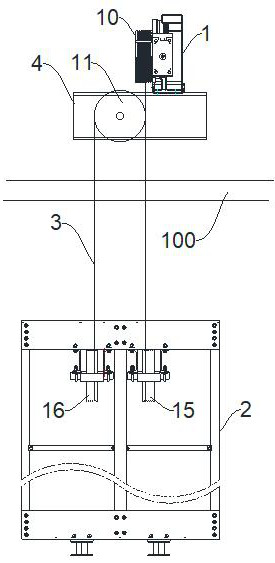
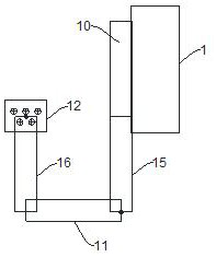
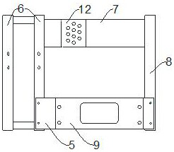
[0021] Such as Figure 1 to Figure 4 As shown, an energy-saving freight elevator traction system, the traction ratio of the traction system is 4:1, the traction system includes a traction frame, traction machine 1, counterweight frame 2 and traction rope 3;

[0022] The traction frame includes a load-bearing beam arranged in the hoistway and above the machine room floor 100, and a main frame 4 installed on the load-bearing beam, a car guide wheel and a car rope head plate; Between the frame 4 and the car rope head plate, the main frame 4 is detachably fixed on the top o...


PUM


Abstract

The invention discloses an energy-saving freight elevator traction system. The traction ratio of the traction system is 4: 1, and the traction system comprises a traction rack, a traction machine, a counterweight frame and a traction rope; and the traction rack comprises a bearing beam and a main machine frame installed on the bearing beam. The main machine frame comprises a first frame, a second frame, a third frame and a fourth frame which are sequentially connected end to end, the traction machine is installed on the first frame and connected with a traction sheave, a counterweight guide wheel is arranged on the second frame, the axis of the counterweight guide wheel is perpendicular to the axis of the traction sheave, and a counterweight rope hitch plate is arranged on the third frame. A counterweight diversion sheave assembly is installed in the middle of an upper beam of the counterweight frame and comprises two counterweight diversion sheaves which are coaxial, the axes of the counterweight diversion sheaves are parallel to the horizontal center line of the counterweight frame, and the axes of the counterweight diversion sheaves are parallel to the axis of the traction sheave. According to the energy-saving type freight elevator traction system, the length size of the counterweight frame is effectively reduced, and therefore the requirement for the depth of a hoistway is lowered.

Description

technical field [0001] The invention relates to an energy-saving cargo elevator traction system. Background technique [0002] In the existing 4 to 1 freight elevator, the traction machine, the car top wheel, and the counterweight wheel are vertically distributed up and down, and the installation position and style are fixed, which cannot be adjusted according to the actual civil work. The construction is relatively fixed and is easily affected by the use environment. It cannot be used due to the limitation of the elevator, and the application range is narrow; and it takes up a lot of space, the elevator counterweight to the depth of the shaft (the depth of the shaft refers to the length of the shaft perpendicular to the side of the elevator door in the top view of the shaft, that is to say, in the vertical The length of the hoistway in the direction of the elevator door) has high requirements. Therefore, the existing 4 to 1 freight elevator has the problems of complex stru...

Claims


Application Information

Patent Timeline
Patent Type & Authority Applications(China)
IPC IPC(8): B66B11/00B66B11/04B66B17/12B66B7/06
CPCB66B11/0035B66B11/0065B66B17/12B66B7/06
Inventor 徐斌沈凯莫宇杰叶嘉健
Owner DESENK ELEVATOR CHINA
Why Eureka
Try Eureka