Formwork cleaning device for constructional engineering

A cleaning device and construction engineering technology, applied in the treatment of formwork, construction, building structure, etc., can solve the problems of increasing labor intensity of workers, needing manual cleaning, incomplete cleaning, etc., achieving good brushing effect and firm fixation. Reliable, improved scrubbing efficiency

Pending Publication Date: 2022-01-14
牛犇
13 Cites 0 Cited by

AI-Extracted Technical Summary

Problems solved by technology

[0004] The purpose of the present invention is to provide a formwork cleaning device for construction engineering. Through the use of cleaning structure, gear plate and first pressure pl...

Abstract

The invention discloses a formwork cleaning device for constructional engineering, and relates to the technical field of formwork cleaning. The device comprises a base structure. The base structure comprises a base, wherein two stand columns are fixed to the upper surface of the base, a rectangular groove is formed in one side surface of each stand column, first cylindrical grooves are formed in the positions, between every two adjacent stand columns, of the upper surface of the base, second cylindrical grooves are formed in the upper surface of the base at equal intervals, and supporting rods are fixed to the inner walls of the second cylindrical grooves; a first driving mechanism is mounted at the top of the stand column, the output shaft end of the first driving mechanism penetrates through the stand column and extends into the rectangular groove, a threaded rod rotatably matched with the stand column is fixed to the output shaft end of the first driving mechanism, and a supporting plate structure is in threaded connection with the outer surface of the threaded rod and comprises a first fixing plate. By using the cleaning structure, a gear disc and a first pressing plate, the problem that the labor intensity of the workers is increased as an existing building formwork needs to be manually cleaned after being used, is cleaned halfway and is low in cleaning efficiency is solved.

Application Domain

Form treatment

Technology Topic

Board structureIndustrial engineering +3

Image

  • Formwork cleaning device for constructional engineering
  • Formwork cleaning device for constructional engineering
  • Formwork cleaning device for constructional engineering

Examples

  • Experimental program(1)

Example Embodiment

[0029] Next, the technical solutions in the embodiments of the present invention will be described in connection with the drawings of the embodiments of the present invention, and it is understood that the described embodiments are merely the embodiments of the present invention, not all of the embodiments. Based on the embodiments in the present invention, those of ordinary skill in the art will belong to the scope of the present invention without all other embodiments obtained in the preparation of creative labor.
[0030] In the description of the present invention, it is to be understood that the terms "opening", "upper", "lower", "thickness", "top", "in", "within", "within", "around", etc. Indicates the orientation or positional relationship, is intended to facilitate the description of the present invention and simplified description, rather than indicating or implying that the component or element must have a specific orientation, and therefore cannot be understood as limiting the invention. .
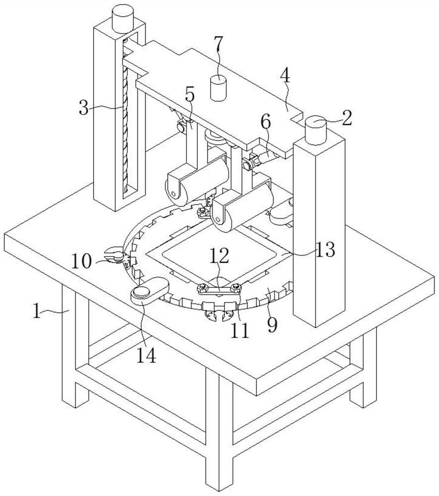
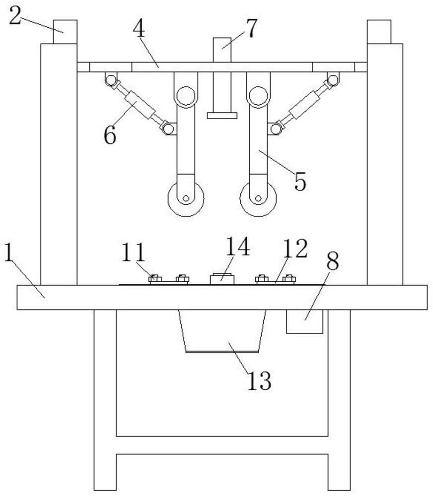
[0031] See Figure 1-8 As shown, the present invention is a shell cleaning device for a building engineering, including a base structure 1, a base structure 1 including a base 101, a base 102, and a rectangular groove 103, a rectangular groove 103, a base 102. The first cylindrical groove 105 is opened on the upper surface and located between adjacent two columns 102, and the upper surface is equipped with a second cylindrical groove 106, and the inner wall of the second cylindrical groove 106 is fixed to the support rod 107.
[0032] The top of the column 102 is mounted with a first driving mechanism 2, and the first drive mechanism 2 outputs the shaft end through the column 102 and extends inside the rectangular recess 103, and the first drive mechanism 2 is fixed to the thread rod 3 that rotates with the column 102. The thickness of the threaded rod 3 is threaded with a support plate structure 4, and the support plate structure 4 includes a first fixing plate 401, and there is a second fixing plate 402 on both sides of the first fixing plate 402, and the second fixing plate 402 is fixed. The third fixing plate 403 threaded with the threaded rod 3, the lower surface of the first fixing plate 401 is fixed to two first ear plate 404, and the lower surface of the second fixing plate 402 is fixed to the second ear plate 405.
[0033] One end of the first ear plate 404 is rotated to be connected to the cleaning structure 5, and the cleaning structure 5 includes a fixing rod 501 that is rotatably blended with the first ear plate 404, and the support frame 503 is fixed at one end, and the support frame 503 is rotated and the roller brush 504 is rotated. The fastener 502 is fixed to the side surface of the fastener 501; one end of the second ear plate 405 is rotatably coupled to the automatic telescopic rod 6 that rotates with the third ear plate 502, and the top of the first fixing plate 401 runs through the spray tube 7.
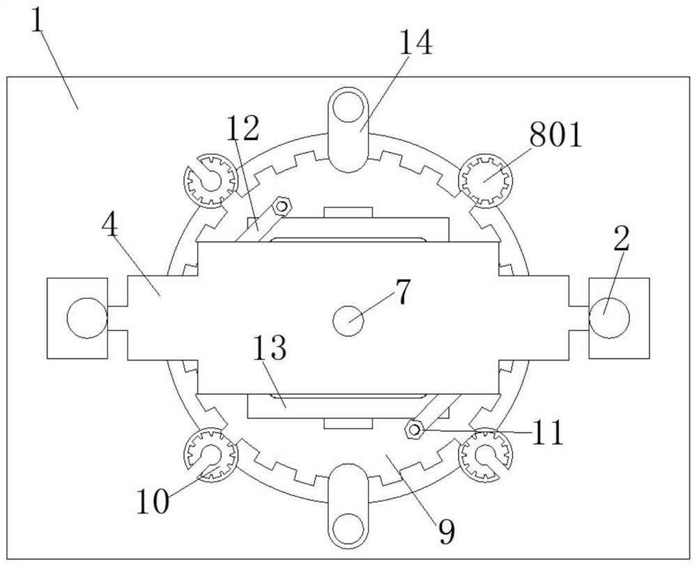
[0034] A second drive mechanism 8 is mounted at the bottom of the base 101, and the second drive mechanism 8 output shaft ends through the second cylindrical groove 106, the second drive mechanism 8 output shaft end fixes the gear 801, the top of the base 101 is rotated with the gear 801 The mating gear disc 9, the position between the lower surface of the support rod 107 and the bottom surface of the second cylindrical groove 106 is rotatably coupled with the driven gear 10 mounted with the gear disc 9.
[0035]The end surface of the gear plate 9 is fixed with four threaded columns 901, and the tank 902 is opened at the top end of the gear disk 9, and the outer surface of the adjacent two threaded column 901 is threaded by the nut 11, and the first pressure plate 12 is connected, and the top of the gear plate 9 passes through the first pressure plate 12. The mold case 13 that is mounted with the accommodating groove 902 is fixed.
[0036] The bottom surface of the first cylindrical groove 105 is equipped with a ball 110, and the bottom surface of the first cylindrical groove 105 is equal to the spherical groove 111 in which the ball 110 is fitted, and the upper surface of the base 101 is fixed with two residential columns 108, the limit The top end of the column 108 fixed a finite disc 109, and the outer surface of the limit column 108 is rotated and connected to the second pressure plate 14 mounted with the gear disc 9, and the first ear plate 404 rotates through the first pin shaft 501 to the fixed lever 501. The second pin plate 405 rotates the connection with the automatic telescopic rod 6 through the second pin shaft.
[0037] The tip of the gear plate 9 is equipped with a rectangular opening 903 through the gear disc 9, wherein the two threads 901 are disposed on the diagonal position of the two threaded columns 901, and the two columns 102 are relatively arranged and located on the same line, the second cylinder. The groove 106 is in communication with the first cylindrical groove 105.
[0038] The penetration hole 104 having the upper surface of the column 102 is formed with the first driving mechanism 2, the through hole 104 is larger than the first driving mechanism 2 output shaft diameter size; the third fixing plate 403 is opened with the threaded rod 3 The threaded hole, the first fixing plate 401 is opened with a mounting hole that cooperates with the spray tube 7.
[0039] A specific application of this embodiment is:
[0040] When used, the mold case 13 is fixed to the gear tray 9 by the first pressure plate 12 and the nut 11, followed by the inlet end of the spray tube 7 to be connected to the water source, and then activates the automatic telescoping rod 6 to adjust the cleaning structure 5 opposite mold shell. 13 of the position, secondly open the power supply driving the first drive mechanism 2, by rotating the threaded rod 3 by the first driving mechanism 2, the support plate structure 4 is driven up and down, and the support plate structure 4 is moved up and down, and the cleaning structure 5 is moved up and down. The mold case 13 is cleaned, and after the cleaning is completed, the position of the mold case 13 can be changed to clean the mold case 13, and after the cleaning is completed, the second drive mechanism 8 is driven, and the second drive mechanism 8 can drive the gear plate 9 to rotate Further, the mandrel 13 is rotated, and the moisture of the shell 13 is dried, and the structure is used, the worker's labor intensity is reduced, and the position of the mold shell 13 is fixed and is not easy to loose.
[0041] In the description of the present specification, a description of the reference terms "an embodiment", "Example", "Specific Examples", etc. One embodiment or in the example. In the present specification, the meaning of the above term is not necessarily referred to as the same embodiments or examples. Moreover, the specific features, structures, materials or features described may be combined in any one or more embodiments or examples.
[0042] The preferred embodiments of the invention disclosed above are only used to help illustrate the invention. The preferred embodiment does not detail all details, nor does not limit the embodiments of the invention. Obviously, according to the content of this specification, many modifications and changes can be made. The present specification is selected and specifically described, in order to better explain the principles and practical applications of the present invention, so that those skilled in the art can understand and utilize the present invention well. The present invention is limited only by the claims and the entire range and equivalents.

PUM

no PUM

Description & Claims & Application Information

We can also present the details of the Description, Claims and Application information to help users get a comprehensive understanding of the technical details of the patent, such as background art, summary of invention, brief description of drawings, description of embodiments, and other original content. On the other hand, users can also determine the specific scope of protection of the technology through the list of claims; as well as understand the changes in the life cycle of the technology with the presentation of the patent timeline. Login to view more.

Similar technology patents

Spot welding system of air-conditioner backboard robot

ActiveCN104874907AMeet production takt requirementsReduce labor intensity
Owner:SHANGHAI XINSHEN METALWORK

Automatic washing equipment of metro vehicle

ActiveCN104890642AComprehensive cleaninggood scrubbing effect
Owner:CHINA RAILWAY DESIGN GRP CO LTD

Full-automatic watering vehicle

Owner:QINGDAO LANNONGGU AGRI PROD RES & DEV

Filtering, cleaning, drying three-in-one device

InactiveCN101455918AReduce labor intensity
Owner:WUXI ZHANGHUA MEDICAL EQUIP

Classification and recommendation of technical efficacy words

  • Reduce labor intensity
  • good scrubbing effect

Method for intelligent automatic identification of transmission circuit parts

Owner:INFORMATION COMM COMPANY STATE GRID SHANDONG ELECTRIC POWER +2

City regional railway signal system and control method thereof

Owner:CHINA RAILWAY SIYUAN SURVEY & DESIGN GRP

Railway bearing intelligent on-line detection method and its device

InactiveCN101290265AReduce labor intensity
Owner:洛阳铭昊测控科技有限公司

Automatic washing equipment of metro vehicle

ActiveCN104890642AComprehensive cleaninggood scrubbing effect
Owner:CHINA RAILWAY DESIGN GRP CO LTD
Why Eureka
Try Eureka