
Medical instrument automatic cleaning device

A medical device and automatic cleaning technology, applied in the field of medical devices, can solve the problems of good cleaning effect, lack of fixing measures, low efficiency, etc. Effect

Pending Publication Date: 2021-07-09
冯定
View PDF2 Cites 3 Cited by
  • Summary
  • Abstract
  • Description
  • Claims
  • Application Information

AI Technical Summary

Problems solved by technology

[0004] A device that can automatically clean medical instruments proposed by the present invention solves the problem of the lack of better fixing measures when cleaning existing medical instruments, which requires manual operation to place and fix, which is less efficient, and cannot clean tightly adhered impurities. The problem of good cleaning effect

Method used


Image

  • Medical instrument automatic cleaning device
  • Medical instrument automatic cleaning device
  • Medical instrument automatic cleaning device

Examples


Embodiment 1

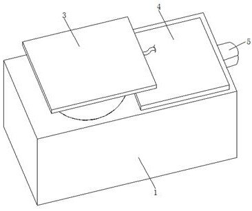
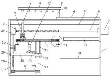
[0031] refer to Figure 1-4 : A device capable of automatically cleaning medical instruments, comprising a box body 1, the top of the box body 1 is rotatably connected to a rotating shaft 2, the top of the rotating shaft 2 is fixedly connected to a water spray head 3, and the bottom outer fixed sleeve of the rotating shaft 2 is provided with a cover plate 4. A drive motor 5 is fixedly connected to the outer wall on the right side of the box body 1, and a reciprocating cleaning mechanism is fixedly connected to the output shaft of the drive motor 5, and a transmission shaft 11 connected to the bottom inner wall of the box body 1 is provided below the reciprocating cleaning mechanism. The external movable sleeve of the transmission shaft 11 is provided with a steering clamping mechanism, and the left side of the steering clamping mechanism is provided with a transmission lifting mechanism that is rotatably connected to the bottom inner wall of the box body 1, and the right inner ...

Embodiment 2

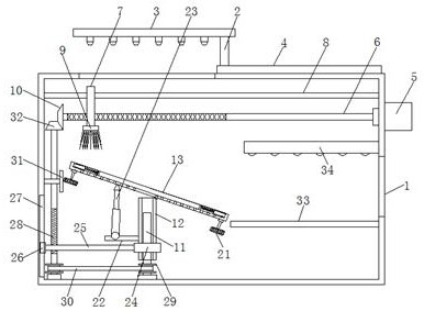
[0039] refer to image 3 , Figure 5-7 : A device that can automatically clean medical instruments. In this embodiment, when the driving motor 5 drives the reciprocating screw rod 6 to rotate counterclockwise, it will drive the first bevel gear 10 to rotate, and the first bevel gear 10 will drive the fourth bevel gear meshed with it. The bevel gear 32 rotates, and the fourth bevel gear 32 drives the second screw rod 28 to rotate. The rotation of the second screw rod 28 will drive the horizontal plate 25 to move down, and the horizontal plate 25 will drive the bearing 24 and the casing 12 to move down. When moving through the rack 31, it will drive the first screw 17 to reverse, so that the splint 18 can be separated, thereby releasing the fixation of the medical device. At this time, the push rod motor 23 will lift the placement tray 13, and the placement tray 13 will tilt , so that it is convenient for the medical device to slide onto the material receiving plate 33 for dryi...


PUM


Abstract

The invention discloses a medical instrument automatic cleaning device, relates to the technical field of medical instruments, and aims to solve the problems that when the medical instruments are cleaned in the prior art, good fixing measures are lacked, manual operation, placement and fixation are needed, consequently the efficiency is low, and a good cleaning effect cannot be achieved on impurities in tight adhesion during cleaning. According to the scheme, the device comprises a box body, a rotating shaft is rotationally connected to the top of the box body, a water sprayer is fixedly connected to the top of the rotating shaft, the bottom of the rotating shaft is fixedly sleeved with a cover plate, a driving motor is fixedly connected to the outer wall of the right side of the box body, and a reciprocating cleaning mechanism is fixedly connected to an output shaft of the driving motor. According to the device, the instruments are convenient to fix and loose automatically, the medical instrument cleaning efficiency is improved, the cleaning quality is improved through flushing and scrubbing cleaning, the whole device is driven by one engine, the integration degree and the automation degree are high, and the device is suitable for market popularization.

Description

technical field [0001] The invention relates to the technical field of medical instruments, in particular to a device capable of automatically cleaning medical instruments. Background technique [0002] Medical devices refer to instruments, equipment, utensils, in vitro diagnostic reagents and calibrators, materials, and other similar or related items that are directly or indirectly used on the human body, including required computer software. [0003] The cleaning tank and discharge generation are disclosed in the comparative document of the medical instrument cleaning device proposed by the authorized announcement number CN103096783B. An endoscope to be cleaned is housed in a cleaning tank and immersed in cleaning water. The discharge unit of the discharge generator is installed in the cleaning tank and is in a state of being immersed in cleaning water. A pair of electrodes of the discharge unit is connected to a DC power supply. When a DC power supply applies a voltage...

Claims


Application Information

Patent Timeline
Patent Type & Authority Applications(China)
IPC IPC(8): B08B1/00B08B3/02B08B13/00
CPCB08B3/02B08B13/00B08B1/12
Inventor 冯定陈伟健黄伟杰李晶张洋铭
Owner 冯定
Learn More