
Electric bone drill

An electric bone drill and bone drill technology are applied in the field of orthopedic bone drilling, which can solve the problems of inability to effectively control the drilling depth, inability to control the drilling feed amount, and inability to feed the drilling at a constant speed, so as to facilitate flushing and feeding. The effect of reducing displacement and reducing the continuous generation of heat

Inactive Publication Date: 2022-06-03
彭强
View PDF0 Cites 1 Cited by
  • Summary
  • Abstract
  • Description
  • Claims
  • Application Information

AI Technical Summary

Problems solved by technology

[0004] The purpose of the present invention is to solve the problems in the prior art that the doctor cannot control the drilling feed rate, cannot feed the drilling at a uniform speed, cannot effectively control the drilling depth and will slip when performing orthopedic drilling in the prior art. electric bone drill

Method used


Image

  • Electric bone drill
  • Electric bone drill
  • Electric bone drill

Examples


Embodiment 1

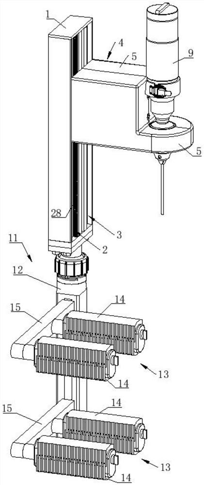
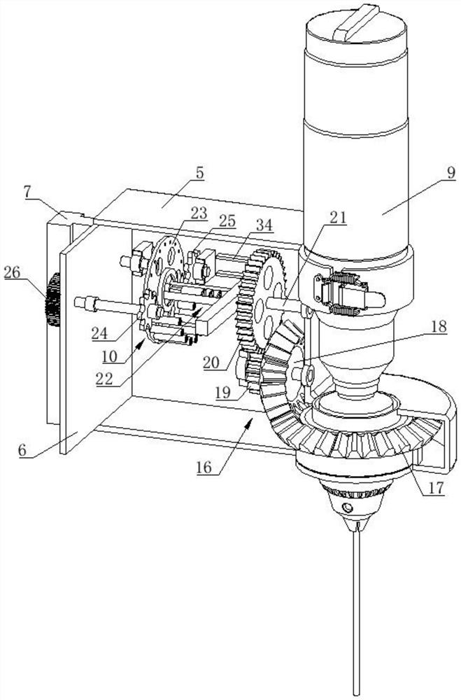
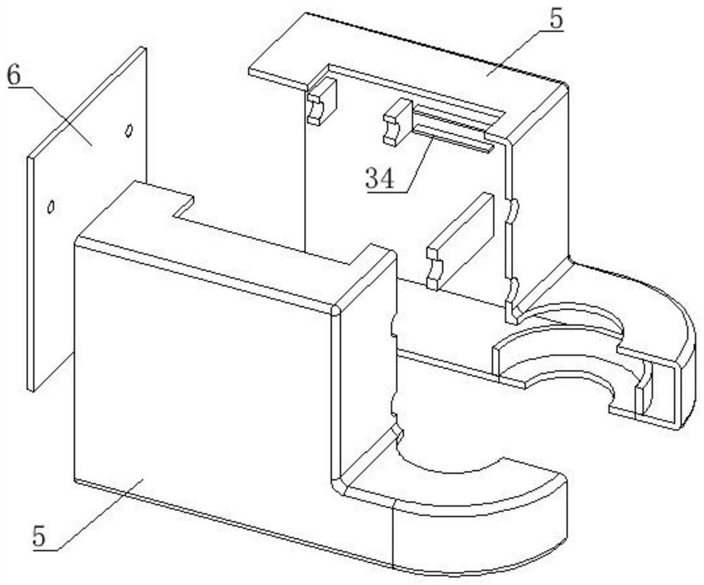
[0040] refer to figure 1 and figure 2 , an electric bone drill, comprising a mounting frame 1, a mounting housing 4, a bone drill body 9, a deceleration assembly 16, and a displacement assembly 10. The mounting housing 4 is integrally slidably arranged on one side of the length direction of the mounting frame 1, and the mounting housing 4 includes a half shell 5 and an end cover 6, the two half shells 5 and the end cover 6 are assembled into the entire installation shell 4, the outer side of the end cover 6 is fitted with the side of the mounting frame 1, and the outer side of the end cover 6 A T-shaped sliding block 7 is provided, and the side of the corresponding mounting frame 1 is provided with a T-shaped sliding groove 8 along its length direction. The T-shaped sliding block 7 is slidably fitted in the T-shaped sliding groove 8. 10 are arranged inside the installation housing 4, the bone drill body 9 is detachably mounted on the deceleration assembly 16, and the deceler...


PUM


Abstract

The invention discloses an electric bone drill which comprises a mounting frame, a mounting shell, a speed reduction assembly, a displacement assembly and a bone drill body, the speed reduction assembly is arranged in the mounting shell, the bone drill body is detachably mounted on the mounting shell, the speed reduction assembly is used for reducing the rotating speed of a drill bit clamp of the bone drill body, and the displacement assembly is in transmission connection with the speed reduction assembly. The displacement assembly drives the installation shell and the bone drill body to move in a reciprocating mode, the moving feeding amount of the bone drill body is always larger than the backward displacement amount of the bone drill body, the feeding amount of the bone drill body is reduced after each reciprocating movement, the installation shell is installed on the installation frame in a sliding mode, and the installation frame is fixed to an operating table or an affected part of a patient. The problems that in the prior art, when a doctor holds a bone drill by hand to conduct orthopedic drilling, the drilling feeding amount cannot be controlled, drilling cannot be conducted at a constant speed, the drilling depth cannot be effectively controlled, and the slipping phenomenon occurs are solved.

Description

technical field [0001] The invention belongs to the technical field of orthopedic bone drills, and in particular relates to an electric bone drill. Background technique [0002] In orthopaedic external fixation, orthopedic internal fixation, neurosurgical craniotomy, and joint replacement or repair, in order to fix implants, plates, or expand the surgical field of view, it is necessary to form a hole or cavity interface in the patient's bone. Use a bone drilling tool. [0003] Due to the different conditions of the patient's disease, doctors often need to hold an electric bone drill to drill during the operation. Since the bones are mostly curved surfaces, the drill bit will slip after contacting the bone and cannot be aligned with the predetermined drilling position. During the process, most of the drilling is carried out by the doctor through the hand-held electric bone drill. The doctor's arm maintains a posture for a long time, which causes the arm muscle fatigue and ca...

Claims


Application Information

Patent Timeline
Patent Type & Authority Applications(China)
IPC IPC(8): A61B17/16
CPCA61B17/1615A61B17/1622A61B17/1626A61B17/162
Inventor 彭强
Owner 彭强
Learn More