Electromagnetic clutch peristaltic pump

An electromagnetic clutch and peristaltic pump technology, applied in the field of peristaltic pumps, can solve the problems of complex structure and large volume, and achieve the effect of convenient replacement of water pipes

Active Publication Date: 2022-01-14
GUANGZHOU MAIGUANG ELECTRONIC TECHNOLOGY CO LTD
View PDF6 Cites 0 Cited by
  • Summary
  • Abstract
  • Description
  • Claims
  • Application Information

AI Technical Summary

Problems solved by technology

[0003] In view of the defects in the above-mentioned prior art that there is only a single pump tube or fixed multi-pump tubes, the volume is large and the structure is complex, and it is impossible to select one or multiple channels from multiple channels for operation, the present invention provides an electromagnetic clutch peristaltic pump. To overcome the above shortcomings

Method used


Image

  • Electromagnetic clutch peristaltic pump
  • Electromagnetic clutch peristaltic pump
  • Electromagnetic clutch peristaltic pump

Examples


Embodiment 1

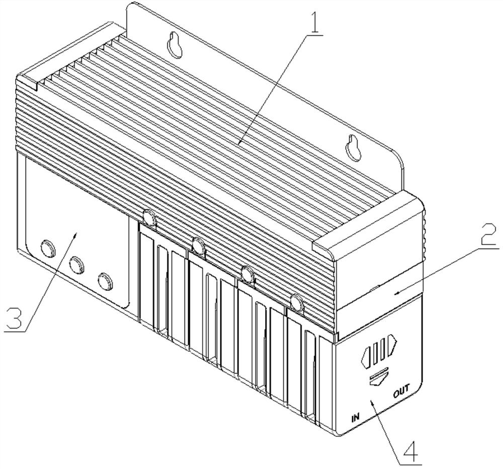
[0030] refer to Figure 1-11 , the present embodiment 1 provides an electromagnetic clutch peristaltic pump, including a mounting frame 1, a transmission device 2, a power device 3, a mounting plate 5 and several peristaltic pump heads 4; the mounting plate 5 is arranged on the inside of the mounting frame 1; The mounting plate 5 is threadedly connected with the mounting frame 1; the transmission device 2 and the power device 3 are all threaded on the mounting plate 5; the peristaltic pump head 4 is detachably connected with the transmission device 2; each of the peristaltic pump heads 4 are independently controlled by the transmission device 2; with this scheme, one or more of the peristaltic pump heads 4 can be independently controlled, and the forward and reverse, timing, and quantitative control of the peristaltic pump heads 4 can also be achieved. Each peristaltic pump head 4 It can be disassembled separately for easy replacement of water pipes.

[0031] In this embodime...

Embodiment 2

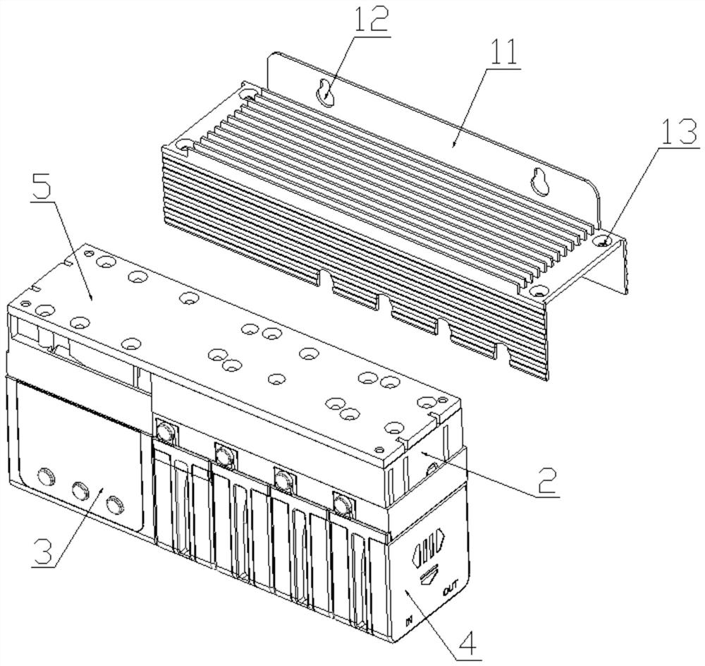
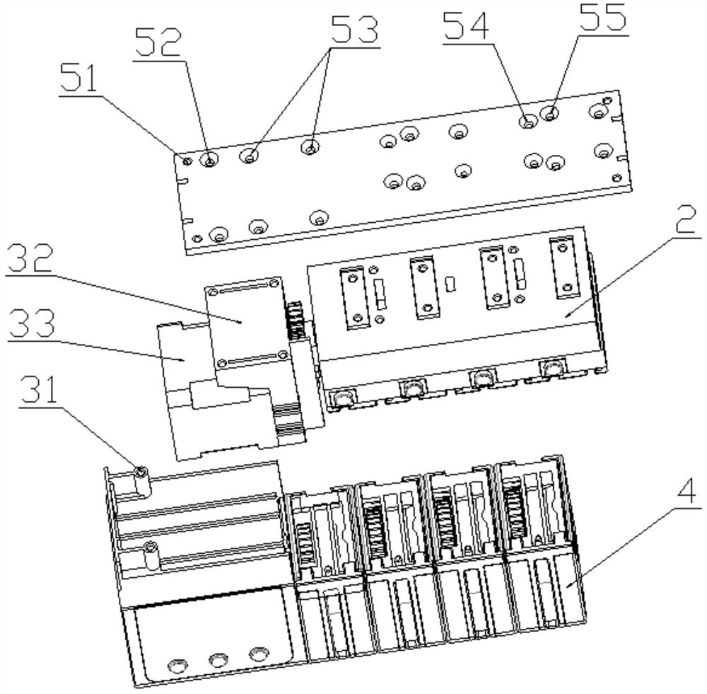
[0036] refer to Figure 1-11 , this embodiment 2 includes all the technical features of implementation 1, the difference is: a flange 11 is provided at the edge of the mounting frame 1; a first mounting slot 12 is symmetrically opened on the flange 11, which is convenient for the whole peristaltic pump fixed installation; the four corners of the mounting frame 1 are provided with a first mounting hole 13; the four corners of the mounting plate 5 are provided with a fourth mounting hole 51 corresponding to the first mounting hole 13; the mounting plate 5 It is fixed with the mounting frame 1 through bolt connection.

[0037] In this embodiment, the mounting plate 5 is further provided with a fifth mounting hole 52 , a sixth mounting hole 53 , a seventh mounting hole 54 and an eighth mounting hole 55 .

[0038] In this embodiment, the motor box is provided with connecting studs 31; the connecting studs 31 are set correspondingly to the fifth mounting hole 52 and are fixed by bo...

Embodiment 3

[0042] refer to Figure 1-11 , this embodiment 3 includes all the technical features of Embodiment 1, the difference is: the electromagnetic clutch peristaltic pump also includes a cover plate 6; one end of the cover plate 6 is provided with a third block 61, and the other end is provided with a third card slot 62 ; The third clamping block 61 is matched with the first clamping slot 210 , and the third clamping slot 62 is matched with the first clamping block 211 .

[0043] With this solution, when the peristaltic pump head 4 is separated from the transmission device 2, the cover plate 6 can be covered on the station to prevent the transmission gear 28 from being exposed to the outside world and prevent dust from entering the transmission device 2 and causing damage to components.


PUM


Abstract

The invention particularly discloses an electromagnetic clutch peristaltic pump which comprises a mounting frame, a transmission device, a power device, a mounting plate and a plurality of peristaltic pump heads. The mounting plate is arranged on the inner side of the mounting frame, the mounting plate is in threaded connection with the mounting frame, the transmission device and the power device are both mounted on the mounting plate in a threaded manner, the peristaltic pump heads are detachably connected with the transmission device, and each peristaltic pump head is independently controlled by the transmission device. One or more peristaltic pump heads can be independently controlled, forward and reverse rotation, timing and quantitative control of the peristaltic pump heads can be achieved, each peristaltic pump head can be independently detached, and a water pipe is convenient to replace.

Description

technical field [0001] The invention relates to the technical field of peristaltic pumps, in particular to an electromagnetic clutch peristaltic pump. Background technique [0002] At present, there are many types of peristaltic pumps in our country, which are usually used in flow measuring instruments, medical equipment, chemical industry, and pharmaceutical industry. Peristaltic pumps are often used for quantitative absorption of reagents, samples or reaction mixtures. The peristaltic pumps in the prior art basically install the rollers directly on the roller frame. When the roller frame rotates, the rollers are driven to revolve with the roller frame, and the rollers themselves also rotate, and the rollers are in the process of revolution and rotation. Some of these roller frames squeeze and release the pump tubing to allow pumping. The existing peristaltic pumps on the market only have a single pump tube or fixed multi-pump tube products, most of which squeeze and relea...

Claims


Application Information

Patent Timeline
Patent Type & Authority Applications(China)
IPC IPC(8): F04B43/12F04B49/00F04B53/22
CPCF04B43/12F04B43/1238F04B43/1223F04B49/00F04B53/22
Inventor 梁卫昕
Owner GUANGZHOU MAIGUANG ELECTRONIC TECHNOLOGY CO LTD
Why Eureka
Try Eureka