
Intelligent control method for stirrer

An intelligent control and mixer technology, applied in the direction of electrical program control, sequence/logic controller program control, etc., can solve the problems of large mixing tools and sealed tanks, increased equipment costs, uneven mixing, etc., to achieve Improve the stirring effect, prevent frequent switching, and improve the effect of recognition accuracy

Pending Publication Date: 2022-01-14
北京科瑞远腾测控技术有限公司
View PDF7 Cites 2 Cited by
  • Summary
  • Abstract
  • Description
  • Claims
  • Application Information

AI Technical Summary

Problems solved by technology

[0002] With the development of industrialization, mixers have been widely used in various industries. The purpose of mixing is to fully mix and fully react the materials to be stirred. The way of mixing is to directly place all the raw materials in a unified mixing tank for mixing. During the mixing process, due to the relatively large gap between the mixing tool and the inside of the sealed tank, uneven mixing is prone to occur. If you want to mix evenly, it takes a long time and the efficiency is relatively low; and the existing mixing equipment is designed to be large One mixing tank corresponds to one mixing tool. If one mixing tank is equipped with two mixing tools, it will not only increase the cost of the equipment, but even if the two mixing tools are used alternately, it is impossible to avoid the problem that a certain mixing tool is used too frequently. As a result, the equipment is aging and the use efficiency of the equipment is reduced. Although there are many control methods for equipment group control in the prior art, there is no intelligent control method designed for mixing equipment with multiple mixing tools. It can not only ensure that each stirring tool is in the best working condition, but also ensure the safety and stability of the entire stirring device

Method used


Image

  • Intelligent control method for stirrer

Examples


Embodiment 1

[0074] Embodiment 1: In the present invention, the process of obtaining the performance identification result of the mixer includes:

[0075] 1) According to the membership functions corresponding to at least two stirring tools, obtain a set of vibration, current, acoustic emission and temperature multi-signal sample data of at least two stirring tools respectively, and bring them into the calculated membership function as input data Obtain the membership degree value of vibration signal, current signal, acoustic emission signal and temperature signal;

[0076] 2) Take the obtained membership degree values ​​of vibration signal, current signal, acoustic emission signal and temperature signal as the basic input value of the basic probability distribution function of D-S evidence theory, and then calculate the basic probability of each air compressor value, the fusion model based on D-S evidence theory is used to fuse the multi-featured sample data of vibration, temperature, pre...


PUM


Abstract

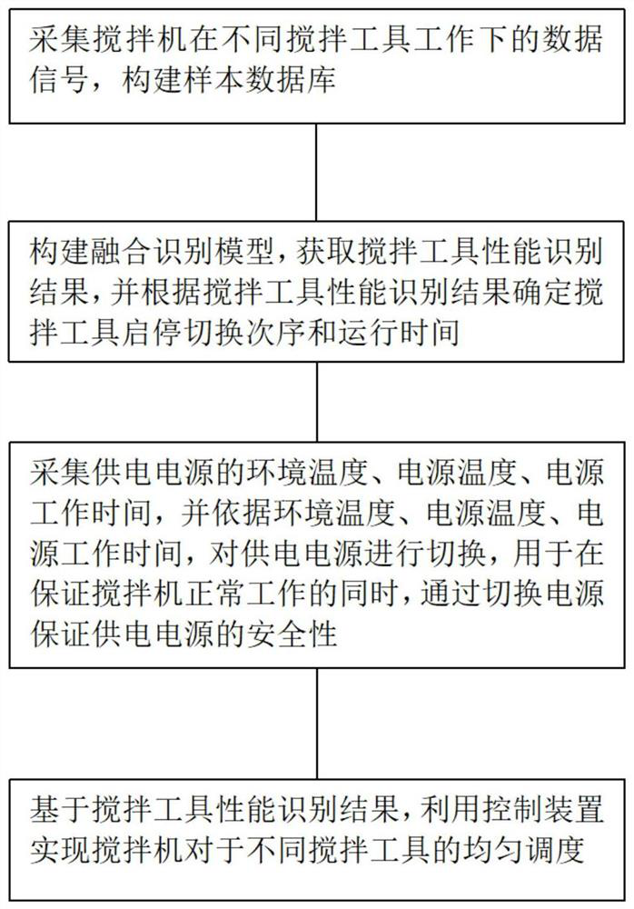
The invention discloses an intelligent control method for a stirrer, which comprises the following steps of: acquiring data signals of a stirrer under the working of different stirring tools, and constructing a sample database; constructing a fusion recognition model, obtaining a stirring tool performance recognition result, and determining a stirring tool start-stop switching sequence and operation time according to the stirring tool performance recognition result; collecting the environment temperature, the power supply temperature and the power supply working time of the power supply, and switching the power supply according to the environment temperature, the power supply temperature and the power supply working time, so that the safety of the power supply is ensured by switching the power supply while the normal work of the stirrer is ensured; and based on the performance identification result of the stirring tool, enabling the stirring machine to uniformly dispatch different stirring tools by using a control device. The technical problem of stirring tool switching of the stirrer with the multiple stirring tools is solved, and a new technical thought is provided for an intelligent control scheme in the technical field of stirrers.

Description

technical field [0001] The present application relates to the technical field of intelligent control, in particular, to an intelligent control method for a mixer. Background technique [0002] With the development of industrialization, mixers have been widely used in various industries. The purpose of mixing is to fully mix and fully react the materials to be stirred. The way of mixing is to directly place all the raw materials in a unified mixing tank for mixing. During the mixing process, due to the relatively large gap between the mixing tool and the inside of the sealed tank, uneven mixing is prone to occur. If you want to mix evenly, it takes a long time and the efficiency is relatively low; and the existing mixing equipment is designed to be large One mixing tank corresponds to one mixing tool. If one mixing tank is equipped with two mixing tools, it will not only increase the cost of the equipment, but even if the two mixing tools are used alternately, it is impossibl...

Claims


Application Information

Patent Timeline
Patent Type & Authority Applications(China)
IPC IPC(8): G05B19/04
CPCG05B19/04
Inventor 武利强
Owner 北京科瑞远腾测控技术有限公司
Learn More