
Device and method for starting a chip in a low-power sensor

A low-power sensor and start-up device technology, which is applied to measuring devices, instruments, data processing power supplies, etc., can solve the problems of increased design difficulty, power supply voltage waveform oscillation, and reduced start-up time, so as to reduce design difficulty and product cost , The power supply voltage waveform is stable, avoiding the effect of shock and overshoot

Active Publication Date: 2022-03-08
SHIJIAZHUANG KE ELECTRIC
View PDF4 Cites 0 Cited by
  • Summary
  • Abstract
  • Description
  • Claims
  • Application Information

AI Technical Summary

Problems solved by technology

In addition, according to the load operation conditions, the power supply voltage waveform will oscillate and overshoot at the moment of switching, so it is necessary to pay attention to the matching of parameters during design, which increases the difficulty of design
[0010] 2. Added switching devices, small-sized products are more sensitive to space, and the added devices make the design more difficult
[0011] 3. After the power supply reaches the threshold, turn on the power supply. According to the chip design requirements, the reset signal still needs to be delayed for a period of time before running. The delay time is generally at the level of 100 milliseconds, which reduces the start-up time and is not suitable for designs that require high start-up time.
[0012] 4. In the scheme of controlling the power supply, the transient response characteristics of the power supply device are highly required. In order to prevent the power supply voltage from being lowered by the momentary load and cause the switch signal to reset and the system to restart, it is necessary to select a power supply device with good performance. increase cost

Method used


Image

  • Device and method for starting a chip in a low-power sensor
  • Device and method for starting a chip in a low-power sensor
  • Device and method for starting a chip in a low-power sensor

Examples


Embodiment Construction

[0030] The present invention will be further described below in conjunction with embodiment.

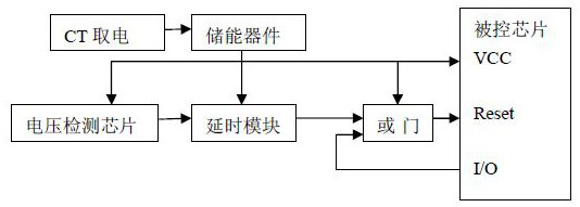
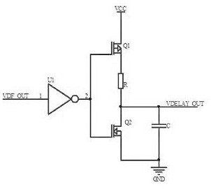
[0031] see figure 1 , the starting device of the chip is essentially a signal generating device, including a voltage detection chip and a delay module. One input terminal of the OR gate is connected, one I / O pin of the controlled chip is connected with the other input terminal of the OR gate, and the output of the OR gate is connected with the Reset pin of the controlled chip.

[0032] In this embodiment, the power supply device is a CT power harvesting device, including a CT power harvesting device and an energy storage device, and the energy storage device is generally a battery or a supercapacitor.

[0033] The starting device of the chip and the controlled chip are provided with working power by the energy storage device.

[0034] The operating voltage of most chips is 5V or 3.3V, and the chip can also work within a certain range near the nominal operating voltage. The lowest ...


PUM


Abstract

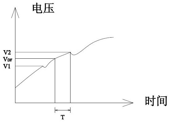
A device and method for starting a chip in a low-power sensor. The chip in a device on a power distribution line starts to work at a higher voltage by delaying the generation of a starting signal. The starting device of the chip includes a voltage detection chip and a delay module, and the voltage output of the power supply device is greater than the detection voltage V DF , the voltage detection chip outputs a high level; when the delay module detects that the level changes from low to high, it triggers timing, and when the timing ends, it outputs a high level, triggering the controlled chip to enter the working state. Adopting the technical scheme of the present invention, according to the characteristics of the power supply and the characteristics of the chip, the chip is started when the appropriate voltage is output, saving time, ensuring that the chip is in a stable state, and will not start frequently; there is no switch in the power supply line, which avoids the need for a switch to turn on. The problems such as vibration and overshoot that come from it can be reduced, and the design difficulty and product cost are reduced; the chip changes from the reset state to normal operation, and the waveform of the power supply voltage is relatively stable during this period.

Description

technical field [0001] The invention relates to the field of chip control, in particular to a circuit and a method for starting a chip in a sensor device on a distribution line to start working at a higher voltage by delaying generation of a starting signal when CT is powered on a distribution line. Background technique [0002] With the development of electric power technology, there are more and more electrical equipment working on high-voltage transmission lines, such as on-line devices such as power line online detection, line equipment anti-theft, low-power environmental monitoring sensors, etc. The power supply generally uses CT to take power device. [0003] The CT power acquisition device generally includes CT power acquisition equipment and an energy storage device. The energy storage device is a battery or capacitor, and the energy storage device is connected to an online device to supply power for it. [0004] The current obtained by CT power-taking equipment is ...

Claims


Application Information

Patent Timeline
Patent Type & Authority Patents(China)
IPC IPC(8): G06F1/26G06F1/3206
CPCG06F1/263G06F1/3206
Inventor 翟志国孙涛杨松杜瑞冰周文骞陆志远李春海王鹏王琳刘义粉
Owner SHIJIAZHUANG KE ELECTRIC
Learn More