Alarm method and system and storage medium

An alarm system and alarm area technology, applied in alarms, anti-theft alarms, instruments, etc., can solve the problems of being unable to accurately identify whether a moving target is a person or a vehicle, wasting labor costs, and dim light, etc., to improve recognition accuracy , improve accuracy and avoid misidentification

Pending Publication Date: 2022-01-14
国能榆林能源有限责任公司 +1
20 Cites 0 Cited by

AI-Extracted Technical Summary

Problems solved by technology

Manual monitoring not only wastes labor costs, but also may cause omissions. Although image recognition reduces the omissions, the environment such as the...

Method used

[0104] The processing component 402 generally controls the overall operation of the alarm system 400, for example, the processing component 402 is used to construct a small-sample target detection network model, a small-sample network classification model, and the like. The processing component 402 may include one or more processors 420 to execute instructions to c...

Abstract

The invention discloses an alarm method and system and a storage medium, which are used for improving the recognition accuracy of human and non-human moving objects in an image so as to avoid a false alarm condition. The method comprises the following steps: acquiring an infrared thermal imaging image containing an alarm area; determining a moving object in the infrared thermal imaging image; determining a target object of which the temperature information is in a preset interval in the moving object; judging whether the target object enters the alarm area or not; and when the target object enters the alarm area, outputting alarm information. By adopting the scheme provided by the invention, the moving objects in the image are determined firstly, and then the target objects of which the temperature information is in the preset interval in the moving objects are determined, so that people and vehicles in the moving objects can be further distinguished through the temperature information, misrecognition of people is avoided, the recognition accuracy of human and non-human moving objects in the image is improved, and then the situation of false alarm is avoided.

Application Domain

Burglar alarm

Technology Topic

Computer visionEngineering +5

Image

  • Alarm method and system and storage medium
  • Alarm method and system and storage medium
  • Alarm method and system and storage medium

Examples

  • Experimental program(1)

Example Embodiment

[0049] The preferred embodiments of the present application will be described below with reference to the accompanying drawings, and preferred embodiments described herein are intended to illustrate and explain the present application only and is not intended to limit the present application.
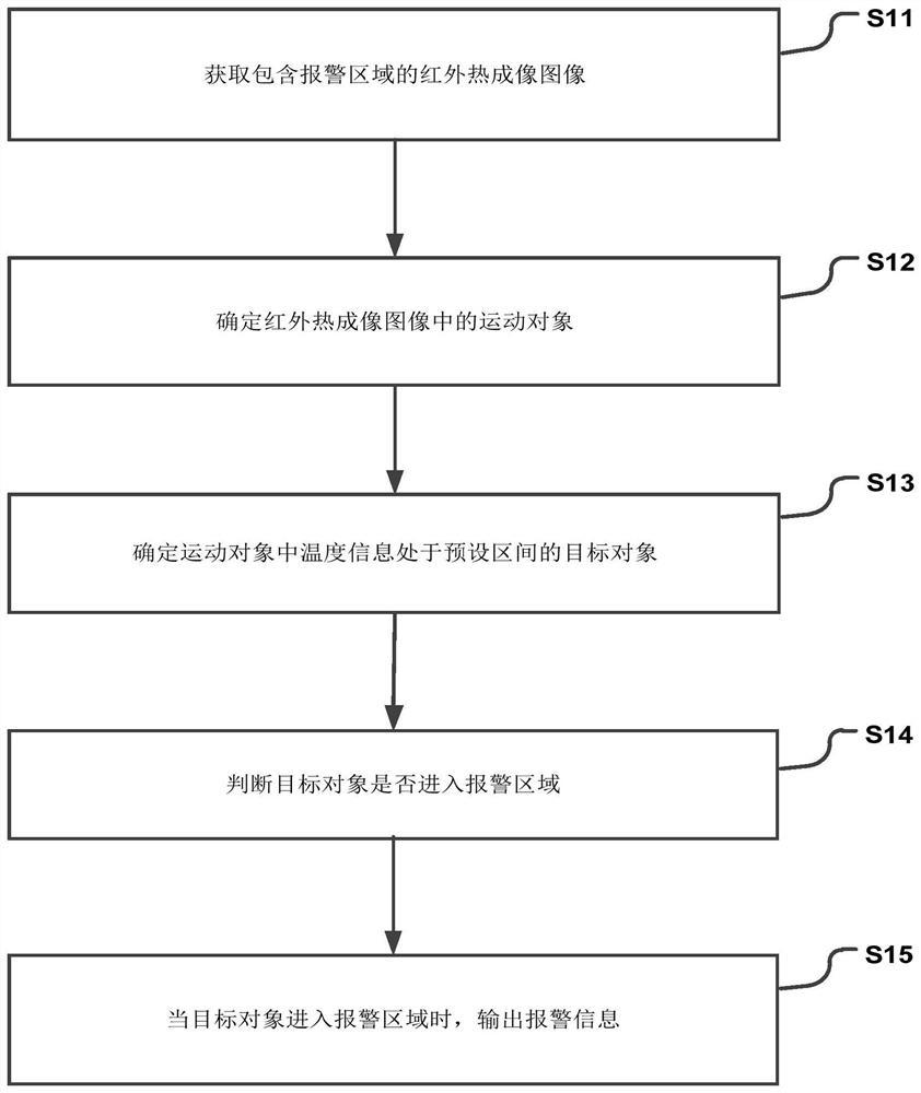
[0050] figure 1 A flow chart of a alarm method in accordance with an embodiment of the present application, such as figure 1 As shown, the method can be implemented as steps S11-S15:
[0051] In step S11, an infrared thermal imaging image containing alarm area is obtained;
[0052] In step S12, the motion object in the infrared thermal imaging image is determined;
[0053] In step S13, it is determined that the temperature information in the moving object is in the target object between the preset interval;
[0054] In step S14, it is judged whether or not the target object enters the alarm area;
[0055] In step S15, when the target object enters the alarm area, the alarm information is output.
[0056] The thermal imaging technique refers to the use of an infrared detector and an optical imaging objective to accept the infrared radiant energy distribution pattern of the detected target to the photosensitive element of the infrared detector, thereby obtaining infrared thermal image chart, such a thermal image diagram with the heat of the object surface The distribution field corresponds to. It is popular that the infrared thermal imagery is a visible thermal image that is not visible to the object. Different colors on the hot image represent different temperatures of the object being measured. The thermal imaging technology is achieved according to all objects. Although many objects can't see from the appearance, there is still a cold and cold. With the color of the hot map, it can be seen that the temperature is distributed, red, and the pink indicates a relatively high temperature, blue and green indicates a lower temperature. The light is visible light, which is an electromagnetic wave that the human eye can feel. The wavelength of visible light is: 0.38-0.78 microns. Electromagnetic waves from 0.38 microns and electromagnetic waves longer than 0.78 microns, people can't feel. Electromagnetic waves from 0.38 microns are located outside the visible photoelectric spectrum, referred to as ultraviolet rays, and is referred to as infrared rays than in the visible light spectrum than the electromagnetic wave of 0.78 microns. Infrared, also referred to in infrared radiation, refers to electromagnetic waves from 0.78 to 1000 microns. A portion where the wavelength is 0.78 to 2.0 microns is called near-infrared, the portion of the wavelength is 2.0 to 1000 microns is called the hot infrared rays. Camera imaging results in a photo, the television camera is imaged to obtain a TV image, all of which are visible light imaging. In the nature, all objects can radiate infrared rays, so the infrared difference between the target itself and the background is used to determine the infrared difference between the target itself and the background, and the image formed by the thermal infrared image is referred to as a heat map. The target's hot image and target visible visible light image are different. It is not the target visible light image that can be seen in the human eye, but the target surface temperature distribution image, in a sentence, infrared thermal imaging makes people's eyes can not directly see the surface temperature of the target Distributed, which can become a thermal image representing the temperature distribution of the target surface. Typically thermal imaging is mainly used for temperature measurement of people, and performs temperature measurement warning monitoring by setting the maximum, minimum value, or average value of the temperature.
[0057]In this application, an infrared thermal imaging image containing alarm area is obtained; specifically, an infrared thermal imaging video containing alarm area transmitted in an infrared thermal imagery located in the alarm area; then intercept infrared thermal imaging video according to preset intervals Multi-frame continuous infrared thermal imaging images.
[0058] Determine the moving object in the infrared thermal imaging image; Sports object. Specifically, after comparing the multi-frame continuous image, the region in which the change in the thermal infrared imaging image is determined according to the comparison result. Assume that the infrared thermal imaging image captures pedestrians, pedestrians relative to camera system in three-dimensional space, will change the imaging of pedestrians in the camera system, which makes the same goal with different images, that is, the location of the pedestrians in the image Different, therefore, when comparing the multi-frame continuous thermal imaging image, a variable region can be obtained, that is, the area containing the pedestrian in the image, which is subsequently extracted.
[0059] In the above steps, it is to find changes in target image characteristics, thereby locating motion objects, and another feature extraction in image recognition is to identify target images that do not change without changes in the target. Characteristics, such characteristics or feature quantities are called invariance or non-variables, respectively. These invariance reflects the same goal or the same target invariant characteristics on visual information, or the nature difference between different modes, the system is easier to classify the correct classification and identification decision, for example, the infrared thermal imagery is The invisible infrared energy emitted by the object is transformed into visible thermal images. Different colors on the hot image represent different temperatures of the object being measured. Under normal circumstances, the pedestrians are in the mobile engineering, and the temperature varies in the mobile engineering. This level of temperature changes are reflected in the color of the thermal image, which is negligible. Since the temperature change produced by the motion object can be ignored, the color of the moving object on the hot image can be seen as an invariance or an invariant. Therefore, in this application, the temperature information in the moving object is determined in the preset interval; specifically, acquires color information of each moving object; determines the temperature of the moving object according to the color information of the moving object; determine the temperature according to the temperature of the moving object The temperature information in the object is in the target object of the preset interval. Among them, the temperature of the moving object is determined according to the color information of the moving object, including: obtaining a corresponding relationship table of the color and temperature of the moving object in the infrared thermal imaging image; the temperature of the moving object is determined according to the color information of the moving object and the corresponding relationship table.
[0060] When the target object enters the alarm area, the alarm information is output.
[0061] If you only determine the moving object, you can't judge that the moving object is a person or the car, and the thermal imaging technology is implemented according to all objects, but encounters ambient temperature and the target object temperature difference or the same time, The difficulty of capturing the target is significantly improved relative to the heat capture target, which reduces the accuracy of the identification difficulty. Based on this, in this application, when the feature extraction, the target image characteristics (i.e., the motion characteristics of the object) have occurred, and it is found that there is no change, the invariant or invariant (ie, the color of the moving object) is found. Thereby, the feature extraction can be made more accurate, and it is possible to more accurately distinguish the image features of the image in the image in the image in the image. In the case where people can more accurately distinguish between people and non-motion objects in the image, the probability of misorbing the vehicle is reduced, thereby reducing the probability of false alarms.
[0062] Next, it is assumed that there are multiple alarms, and the implementation subject (e.g., processor) of the present application can record each alarm area, numbered each alarm area, and then determine if the device in the alarm area is at power-on operation, when alarm When the device in the region is on power-on, the current state of the alarm area where the device in the power-on-power operating state can be changed to the armed state. When the device of the alarm area is in a non-working state, it will be in a non-working state. The current state of the alarm area where the device is located is changed to withdraw. At the time of the alarm, it can be determined whether the alarm area is currently in the arbitrary state. When the alarm area is currently in the armed state, it is determined the residence time of the target object in the alarm area; output alarm when the target object reaches the preset time of the target object information.
[0063] According to the above embodiment, the present scheme uses thermal imaging techniques, mainly for detection and identification of personnel violations such as one or more alarms in the coal mining area, and identify the behavior of personnel to personnel by thermal imaging camera , Alarm reminder for the resulting violation behavior. Specifically, the detection of the personnel by thermal imaging techniques is determined that the temperature information in the infrared thermal imaging image is in the preset interval, for example, the target object can be a staff. The behavior is analyzed by detecting the algorithm, ie, determines whether the target object enters the alarm area by detecting the algorithm. The analysis result is transmitted to the control signal to output. For example, when the target object enters alarm area, the control signal is output to the alarm device to control the alarm device output alarm information, wherein the alarm device can be located in alarm area, which can be a speaker for a speaker.
[0064] Further, in the present application, the apparatus of the alarm area in the image needs to be consistent with the range of the actual alarm area, and the specific alarm area is determined according to the actual operation of the device, for example, in order to avoid the interaction between staff and devices. , The travel route of the device, the active area of ​​the device, etc., can be set to alarm area, and when setting a alarm area, the alarm area can be laid out in an infrared thermal imaging image through one or more edge lines. When the specific identifier is alarm, a single-line manner can be employed, for example, the shape that matches the actual alarm area is labeled in the infrared thermal imaging image through the edge line. Further, the multi-line mode can also be used to identify alarm area, for example, in the peripheral line of the alarm area, that is, the outer circumference of the edge line corresponding to the alarm area, can be set to a warning area that is greater than the alarm area, shape and alarm area, can be set. Simultaneously identify the shape of the alarm area and the shape matching with the warning area, thereby forming a two-line region. When determining if the target object enters alarm area, if the target object enters the warning area, and the target object can be considered to enter the alarm area if the target object enters the warning area.
[0065] The beneficial effect of this application is to first determine the moving object in the image, then determine the target object in the mode of temperature information in the motion object, so that it is possible to further distinguish between the moving object which is a vehicle, avoid People's misunderstandings, improve the accuracy of identification of people and non-human moving objects in the image, thereby avoiding false alarms.
[0066] In one embodiment, the above step S11 can be implemented as steps A1-A2:
[0067] In step A1, an infrared thermal imaging video containing the alarm area is received in the infrared thermal imaging device located in the alarm area;
[0068] In step A2, the multi-frame continuous infrared thermal imaging image in the infrared thermal imaging video is intercepted according to the preset time interval.
[0069] In one embodiment, if figure 2 As shown, the above step S12 can be implemented as steps S21-S23:
[0070] In step S21, a multi-frame continuous thermal imaging image is compared;
[0071] In step S22, a region where the thermal infrared imaging image is changed according to the comparison result;
[0072] In step S23, the moving object in the infrared thermal imaging image is determined based on the changed region.
[0073] In this embodiment, after comparing the multi-frame continuous image, the region where the change in the thermal infrared imaging image is determined according to the comparison result. Assume that the infrared thermal imaging image captures pedestrians, pedestrians relative to camera system in three-dimensional space, will change the imaging of pedestrians in the camera system, which makes the same goal with different images, that is, the location of the pedestrians in the image Different, therefore, when a multi-frame continuous thermal imaging image is compared, a change in the region can be obtained, that is, the area containing the pedestrians in the image, and then extracts the area or its boundary, determines the moving object located within the region according to the region or its boundary. .
[0074] In one embodiment, if image 3 As shown, the above step S13 can be implemented as steps S31-S33:
[0075] In step S31, color information of each moving object is obtained;
[0076] In step S32, the temperature of the moving object is determined according to the color information of the motion object;
[0077] In step S33, the temperature information in the motion object is in the preset interval is determined according to the temperature of the moving object.
[0078] In one embodiment, the above step S32 can be implemented as follows B1-b2:
[0079] In step B1, the correspondence table of the color and temperature of the motion object in the infrared thermal imaging image is obtained;
[0080] In step B2, the temperature of the moving object is determined according to the color information of the moving object and the corresponding relational table.
[0081] In one embodiment, the method can also be implemented as steps C1-C2:
[0082] In step C1, the marking operation of the infrared thermal imaging image is received;
[0083] In step C2, alarm area is recorded in the infrared thermal imaging image based on the edge line.
[0084] The alarm area can be recorded in the infrared thermal imaging image through one or more edge lines. When the specific identifier is alarm, a single-line manner can be employed, for example, the shape that matches the actual alarm area is labeled in the infrared thermal imaging image through the edge line. Further, the multi-line mode can also be used to identify alarm area, for example, in the peripheral line of the alarm area, that is, the outer circumference of the edge line corresponding to the alarm area, can be set to a warning area that is greater than the alarm area, shape and alarm area, can be set. Simultaneously identify the shape of the alarm area and the shape matching with the warning area, thereby forming a two-line region.
[0085] In addition, in some cases, the alarm area is located in the intermediate region of the infrared thermal imaging image, and in some cases, the alarm area can also be adjacent to the edge of the infrared thermal imaging image. For example, when the alarm area is located in the intermediate region of the infrared thermal imaging image, the edge line corresponding to the alarm area can form an irregular closed area in the infrared thermal imaging image. And when the alarm area falls into the infrared thermal imaging image, the edge line of the alarm area may be one or several lines, for example, the left half of the infrared thermal imaging is alarm area, and the right half is a non-alarm area, then the edge The line is a divided line between the alarm area and the non-alarm area in the infrared thermal imaging image. In this case, the direction is required to be configured to configure the direction to the left, analyze the movement of the target object by continuous infrared thermal imaging image. Trend, when the motion trend of the target object is moving in the non-alarm area, it can be determined that the target object is approaching the alarm area. In this case, the distance can be alarm when the distance of the target object is less than the preset distance threshold. No need to wait until the target object enters the alarm area. When the motion trend of the target object is moved to the right in a non-alarm area, it is determined that the target object is moving away from the alarm area.
[0086] Therefore, the present application can also be implemented as: By continuous infrared thermal imaging image analysis target object's motion trend, determine whether the target object is approaching the alarm area according to the motion trend of the target object and the pre-configured direction information, when the target object is approaching The alarm area, and the target object and the alarm area are less than the preset distance threshold, output alarm information.
[0087]In one embodiment, the above step S14 can be implemented as steps D1-D2:
[0088] In step D1, it is judged that the target object is within the edge line corresponding to the alarm area in the infrared thermal imaging;
[0089] In step D2, when the target object is within the edge line in the infrared thermal imaging, the target object enters the alarm area.
[0090] In this application, the crossing and towering mechanism are set, and it is judged whether or not the target object in the infrared thermal imaging is within the edge line corresponding to the alarm area; it is to determine whether the target object is route the edge line corresponding to the alarm area, and the target object in the infrared thermal imaging When it is within the edge line, the target object enters the alarm area.
[0091] Of course, in the above embodiment, the two-wire region is described, and therefore, in the present application, if the thermal imaging image is included in the two-line area, if the target object passes the edge line corresponding to the alert area, it touchs the alarm area The boundary line, determine the target object into the alarm area.
[0092] In one embodiment, the above step S15 can be implemented as steps E1-E3:
[0093] In step E1, it is determined whether the alarm area is currently in a state of arrest;
[0094] In step E2, when the alarm area is currently in the arming state, it is judged that the target object is residence time of the alarm area;
[0095] In step E3, the alarm information is output when the target object reaches the preset time in the residence time of the alarm area.
[0096] In this embodiment, it is determined whether the alarm area is currently in the arbitrary state; when the alarm area is currently in the armed state, it is determined that the target object is a residence time of the alarm area. When the target object reaches the preset time in the residence time of the target object, output alarm information.
[0097] It should be noted that when the target object is in this case inside the alarm area, the set preset time is short, and for example, it can be 1 second, even 0 seconds, and then alarm immediately. When the target object is in an early warning area, and in this case of contact with the edge line of the alarm area, the set preset time can be appropriate, for example, 5 seconds, 8 seconds, and the like.
[0098] The advantageous effect of this embodiment is that only the alarm area is currently in the arbitrary state, and the target object is output when the residence time of the alarm area reaches the preset time, and the alarm information is output, avoiding the alarm area in an disabled state or the target object is smaller than the alarm area. The misoperative alarm caused by a short period of time set, further enhanced the accuracy of the alarm.
[0099] Figure 4 A hardware structure of a alarm system in an embodiment of the present invention. like Figure 4 As shown, including:
[0100] At least one processor 420; and
[0101] Memory 404 connected to the at least one processor 420; wherein
[0102] The memory 404 stores instructions performed by the at least one processor 420, which is performed by the at least one processor 420 to achieve the alarm method described in any of the above embodiments.
[0103] Refer Figure 4 The alarm system 400 can include one or more components: processing assembly 402, memory 404, power component 406, multimedia component 408, audio component 410, input / output (I / O) interface 412, sensor assembly 414, and Communication component 416.
[0104] Processing component 402 typically controls the overall operation of the alarm system 400, for example, for constructing a small sample target detection network model, a small sample network classification model, and the like. Processing component 402 can include one or more processor 420 to perform instructions to complete all or part of the steps of the above method. Additionally, processing assembly 402 can include one or more modules for handling interactions between components 402 and other components. For example, processing assembly 402 can include a multimedia module to facilitate interaction between multimedia component 408 and processing component 402.
[0105] Memory 404 is configured to store various types of data to support operations in the alarm system 400. Examples of this data include instructions for any application or method for operating on the alarm system 400, such as text, pictures, video, and the like. Memory 404 can be implemented by any type of volatile or nonvolatile storage device or a combination thereof, such as static random access memory (SRAM), electrically erasable programmable read only memory (EEPROM), can be erased Programmable Read-Read memory (EPROM), programmable read-only memory (PROM), read-only memory (ROM), magnetic memory, flash memory, disk or disc.
[0106] Power component 406 provides power supplies for various components of the alarm system 400. Power component 406 can include a power management system, one or more power supplies, and other components associated with the alarm system 400 generated, manage, and allocate a power supply.
[0107] Multimedia component 408 includes a screen that provides an output interface between the alarm system 400 and the user. In some embodiments, the screen can include a liquid crystal display (LCD) and a touch panel (TP). If the screen includes a touch panel, the screen can be implemented as a touch screen to receive an input signal from the user. The touch panel includes one or more touch sensors to sense the gestures on the touch, slide, and touch panels. Touch sensors may not only sense the boundaries of touch or sliding operations, but also detect duration and pressure associated with touch or sliding operations. In some embodiments, the multimedia component 408 can also include a front camera and / or a post camera. When the alarm system 400 is in operation mode, such as shooting mode or video mode, the front camera and / or the rear camera can receive the external multimedia data. Each front camera and the rear camera can be a fixed optical lens system or with focal length and optical zoom.
[0108] The audio component 410 is configured to output and / or input an audio signal. For example, the audio component 410 includes a microphone (MIC), when the alarm system 400 is in an operation mode, such as the call mode, the recording mode, and the speech recognition mode, the microphone is configured to receive an external audio signal. The received audio signal can be further stored in memory 404 or transmitted via communication component 416. In some embodiments, the audio assembly 410 also includes a speaker for outputting an audio signal.
[0109] The I / O interface 412 provides an interface between the processing component 402 and the peripheral interface module, and the peripheral interface module can be a keyboard, a clicking wheel, a button, and the like. These buttons can include, but are not limited to: home button, volume buttons, start button, and lock buttons.
[0110] Sensor assembly 414 includes one or more sensors for providing a state assessment of various aspects for the alarm system 400. For example, sensor assembly 414 can include a sound sensor. In addition, the sensor assembly 414 can detect the opening / closing state of the alarm system 400, the relative positioning of the assembly, such as the display and keypad of the alarm system 400, and the sensor assembly 414 can also detect a component of the alarm system 400 or alarm system 400. The location changes, the user and the alarm system 400 contact or does not exist, the alarm system 400 or the temperature of the acceleration / deceleration and the temperature of the alarm system 400 are changed. The sensor assembly 414 can include a proximity sensor configured to detect the presence of nearby objects when there is no physical contact. Sensor assembly 414 can also include a light sensor such as a CMOS or CCD image sensor for use in imaging applications. In some embodiments, the sensor assembly 414 may also include an acceleration sensor, a gyroscope sensor, a magnetic sensor, a pressure sensor, or a temperature sensor.
[0111] The communication component 416 is configured to provide communication capabilities that provide a wired or wireless mode between the alarm system 400 and other devices and the cloud platform. Alarm system 400 can access a communication standard-based wireless network such as WiFi, 2G, or 3G, or a combination thereof. In an exemplary embodiment, communication component 416 receives a broadcast signal or broadcast related information from an external broadcast management system via a broadcast channel. In an exemplary embodiment, communication component 416 also includes a near field communication (NFC) module to facilitate short-range communication. For example, the NFC module can be achieved based on RFI (RFID) technology, infrared data association (IRDA) technology, ultra-wideband (UWB) technology, Bluetooth (BT) technology, and other techniques.
[0112] In an exemplary embodiment, the alarm system 400 can be subject to one or more application dedicated integrated circuit (ASIC), digital signal processor (DSP), digital signal processing device (DSPD), programmable logic device (PLD), on-site Programming Gate Array (FPGA), controller, microcontroller, microprocessor or other electronic component implementation for performing the above alarm method.
[0113] The present application also provides a computer storage medium that enables the alarm system to achieve the alarm method described in any of the above-described embodiments when the instructions in the storage medium correspond to the processor corresponding to the alarm system.
[0114] Those skilled in the art will appreciate that embodiments of the present application can be provided as a method, system, or computer program product. Therefore, the present application may employ a full hardware embodiment, a fully software embodiment, or in the form of a combination of software and hardware embodiments. Moreover, the present application can employ a computer program product that includes a computer available storage medium (including but not limited to disk memory, etc.) in one or more computers (including, but not limited to, disk memory, etc.).
[0115] The present application is described with reference to the method, device (system), and flowcharts and / or block diagrams of the computer program product, in accordance with the present application embodiment. It should be understood that each of the flowcharts and / or blocks in the flowchart and / or block diagram can be implemented by a computer program command, and the binding of the flow and / or box in the flowchart and / or block diagram. These computer program instructions can be provided to generic computers, dedicated computers, embedded processes, or other programmable data processing devices to generate a machine such that instructions executed by the processor of the computer or other programmable data processing device. Implementation in the process Figure one Process or multiple processes and / or boxes Figure one Apparatus specified in a plurality of boxes or multiple boxes.
[0116] These computer program instructions can also be stored in a computer readable memory capable of booting a computer or other programmable data processing device in a particular manner, making the instructions stored in the computer readable memory generate a manufacturing product of the instruction device, which Device is implemented in the process Figure one Process or multiple processes and / or boxes Figure one The function specified in the box or multiple boxes.
[0117] These computer program instructions can also be loaded on a computer or other programmable data processing device such that a series of steps are performed on a computer or other programmable device to generate a computer implemented process, thereby executing on a computer or other programmable device. The instruction is provided for implementation Figure one Process or multiple processes and / or boxes Figure one The step of the function specified in multiple boxes or multiple boxes.
[0118] Obviously, those skilled in the art can make various modifications and variations of the present application without departing from the spirit and scope of the present application. Thus, the present application is also intended to include these modifications and variations if these modifications and variations of the present application are within the scope of the claims and their equivalents thereof.

PUM

no PUM

Description & Claims & Application Information

We can also present the details of the Description, Claims and Application information to help users get a comprehensive understanding of the technical details of the patent, such as background art, summary of invention, brief description of drawings, description of embodiments, and other original content. On the other hand, users can also determine the specific scope of protection of the technology through the list of claims; as well as understand the changes in the life cycle of the technology with the presentation of the patent timeline. Login to view more.

Similar technology patents

Intelligent automobile tail door opening system and method based on cameras inside and outside cabin

PendingCN114495337Aavoid misidentificationReduce vehicle cost
Owner:CHONGQING CHANGAN AUTOMOBILE CO LTD

Unpowered forward cap and reverse cap automatic removal device

PendingCN111232610Aavoid misidentification
Owner:HAIKOU XINJIADA ELECTROMECHANICAL

Turbine operation abnormal data identification method and equipment

PendingCN114329808Aavoid misidentificationimprove accuracy
Owner:STATE GRID HEBEI ENERGY TECH SERVICE CO LTD +2

Information identification system for patent electronic notice file

InactiveCN108230192Aavoid misidentificationImprove recognition efficiency
Owner:安徽行之智汇知识产权运营有限公司

Information prompting method and device based on AR glasses, equipment and storage medium

PendingCN114445878AEasy to recall relevant informationavoid misidentification
Owner:TIANYI TELECOM TERMINALS

Classification and recommendation of technical efficacy words

  • Improve recognition accuracy
  • avoid misidentification

'Internet+' package bottle intelligent recovery system and method

PendingCN106846621Aavoid misidentificationImprove user experience level
Owner:HUNAN UNIV

Character recognition method and device for image, electronic equipment and readable storage medium

PendingCN111476067Aavoid misidentificationImprove precision and recall
Owner:TENCENT TECH (SHENZHEN) CO LTD

Distribution network overhead line fault self-recovery method and system

ActiveCN107612148Aavoid misidentificationReliable fault self-healing
Owner:GUANGXI POWER GRID ELECTRIC POWER RES INST +2

Video monitoring-laser bird repelling integrated device and method based on edge computing

InactiveCN110692619AReduce grid security operation issuesavoid misidentification
Owner:SHANDONG ZHONGSHI YITONG GRP +1

Optical fiber vibration source recognition method, device, and system

InactiveCN105698915Aavoid misidentificationImprove reliability
Owner:惠州市明光实业有限公司
Why Eureka
Try Eureka