
Puncture wire clamp and method for overhauling overhead power distribution equipment without power outage

A technology for piercing wire clips and power distribution equipment, which is applied to overhead line/cable equipment, equipment for connecting/terminating cables, overhead installation, etc. Instability and other problems, to achieve the effect of stable, fast and convenient installation

Inactive Publication Date: 2022-01-14
李玉常
View PDF0 Cites 0 Cited by
  • Summary
  • Abstract
  • Description
  • Claims
  • Application Information

AI Technical Summary

Problems solved by technology

[0003] Because high-voltage lines are spread all over the corners, some areas with complex terrain are not suitable for construction vehicles to enter, and can only be repaired manually. However, the commonly used puncture wire clamps are far away during overhead installation operations and need to be tightened back and forth. There are two bolts on both sides to ensure the stability of the installation. Therefore, the installation of this kind of clamp not only requires the stability of the maintenance personnel to hold it, but also needs to switch the socket wrench back and forth, which consumes more physical strength of the maintenance personnel. Instability, and higher requirements for overall sealing and waterproof performance

Method used


Image

  • Puncture wire clamp and method for overhauling overhead power distribution equipment without power outage
  • Puncture wire clamp and method for overhauling overhead power distribution equipment without power outage
  • Puncture wire clamp and method for overhauling overhead power distribution equipment without power outage

Examples


Embodiment Construction

[0029] Next, the technical solutions in the embodiments of the present invention will be described in connection with the drawings of the embodiments of the present invention, and it is understood that the described embodiments are merely the embodiments of the present invention, not all of the embodiments. Based on the embodiments of the present invention, all other embodiments obtained by those of ordinary skill in the art are in the range of the present invention without making creative labor premise.

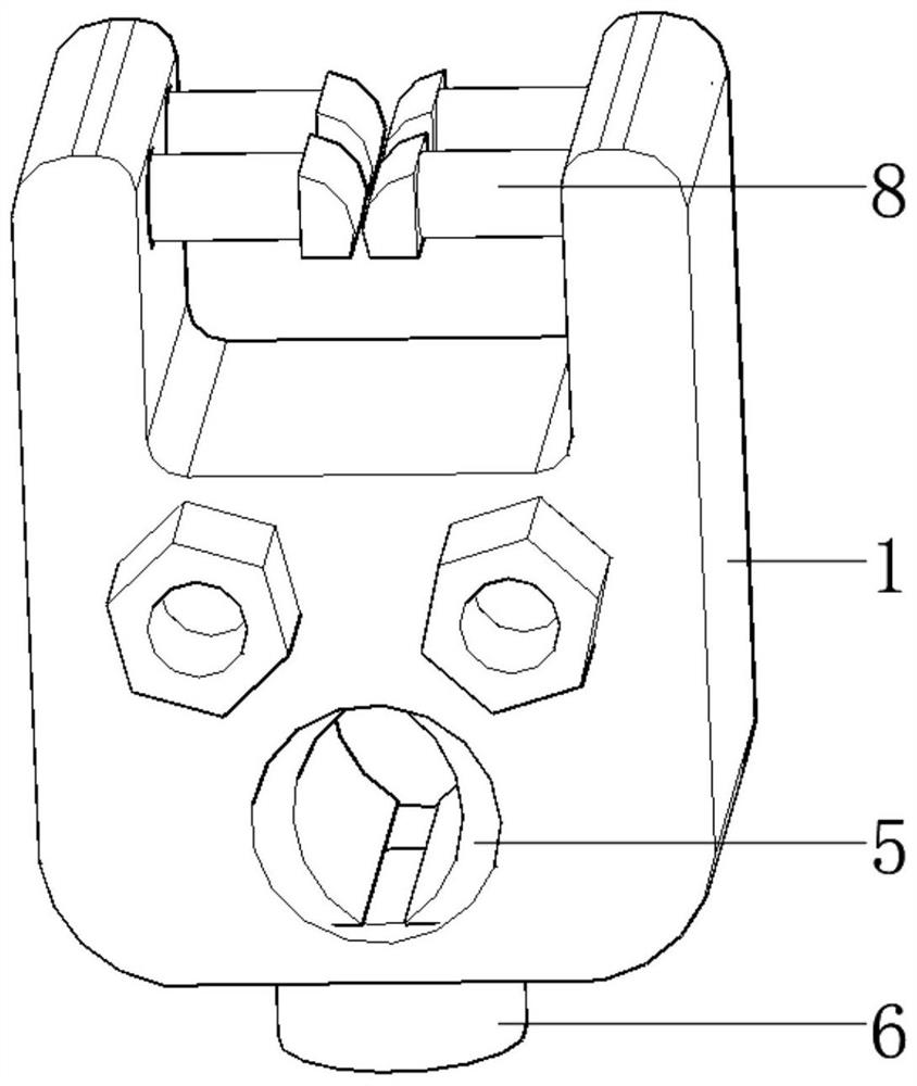
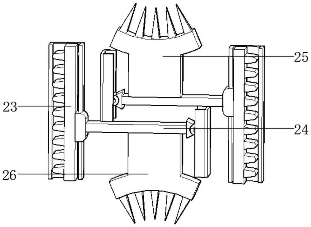
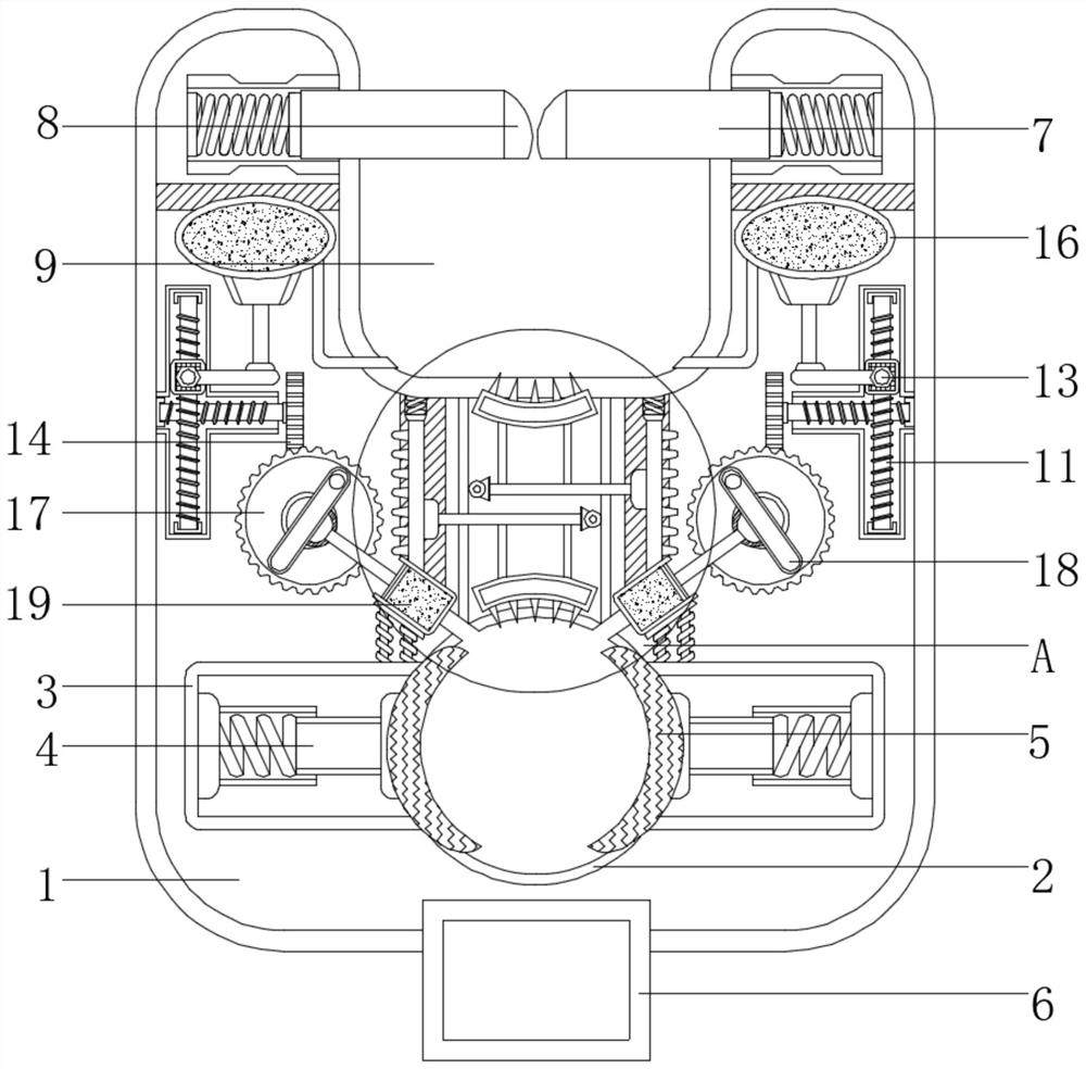
[0030] See Figure 1-3However, the puncture line clip is maintained for the overhead distribution equipment, including the housing 1 and the sleeve wrench 27, and the bottom portion of the housing 1 is opened, and the bottom left and right sides of the casing 1 has a card slot 3. The inside of the card slot 3 is fixedly connected to the telescopic rod 4, and the telescoping rod 4 is fixed to the end of the branch groove 2, and the crescent plate 5 is fixed, and the bottom end of ...


PUM


Abstract

The invention relates to the technical field of power equipment, and discloses a puncture wire clamp for overhauling overhead power distribution equipment without power outage The puncture wire clamp comprises a shell and a socket spanner, a branch wire groove is formed in the bottom of the shell, clamping grooves are formed in the left side and the right side of the bottom of the shell, and telescopic rods are fixedly connected in the clamping grooves; a crescent plate is fixedly connected to the end, close to the branch wire groove, of the telescopic rod, a mounting block is fixedly connected to the bottom end of the shell, stop levers are fixedly connected to the interiors of the left side and the right side of the top end of the shell, touch plates are fixedly connected to the ends, close to the interior, of the stop levers, and the main wire groove is formed in the top of the shell.Through the action of the stop levers, the contact plate and the return spring, the installation is more stable and quick. When the bolt is screwed, the rotating wheel can drive the upper bayonet teeth to pierce the insulating layer of the main wire upwards and drive the lower bayonet teeth to pierce the insulating layer of the branch wire downwards, meanwhile, silicone grease in the air bag and the piston chamber can be squeezed into the main wire groove and the branch wire groove respectively, and waterproof sealing treatment is conducted on the main wire and the branch wire respectively.

Description

Technical field [0001] The present invention relates to the technical field of power equipment, and in particular, a puncture piercing and method for repairing an overhead distribution apparatus. Background technique [0002] With the advancement of the times, today's society is almost done, the laving of high-voltage wires is spread throughout each corner. The high-voltage lines will inevitably have external factors and damage to natural factors, and they generally use them when they overhaul or branch circuits. Thread clip; punch clamp is a piece of accessories commonly used in circuitry and circuit branches, as it cost is relatively low, and it is more convenient, so it is deeply affected by circuit maintenance personnel. [0003] Since the high voltage lines are spread all over the corners, some terrain is not suitable for the entry of the construction vehicle, and can only be repaired by manualization, while the commonly used puncture lines are folded in the overhead install...

Claims


Application Information

Patent Timeline
Patent Type & Authority Applications(China)
IPC IPC(8): H01R4/2407H01R4/2408H02G1/02H02G1/04H02G1/14H02G7/00
CPCH01R4/2407H01R4/2408H02G1/02H02G1/04H02G1/14H02G7/00
Inventor 李玉常
Owner 李玉常
Learn More