Sheet metal stamping equipment

A stamping equipment, sheet metal technology, applied in metal processing equipment, forming tools, manufacturing tools and other directions, can solve the problems of reducing the processing efficiency of sheet metal parts, complicated installation and disassembly of upper and lower molds, and increasing processing time, etc., to improve processing efficiency, The effect of reducing labor intensity and expanding the scope of use

Pending Publication Date: 2022-01-18
赵海东
View PDF0 Cites 2 Cited by
  • Summary
  • Abstract
  • Description
  • Claims
  • Application Information

AI Technical Summary

Problems solved by technology

It can solve the technical problems of the existing sheet metal stamping equipment that the installation and disassembly of the upper and lower dies is complicated. If the stamping form is switched frequently, the processing time will be increased and the processing efficiency of the sheet metal parts will be reduced.

Method used


Image

  • Sheet metal stamping equipment
  • Sheet metal stamping equipment
  • Sheet metal stamping equipment

Examples


Embodiment Construction

[0026] In order to make the technical means, creative features, goals and effects achieved by the present invention easy to understand, the present invention will be further described below in conjunction with specific embodiments.

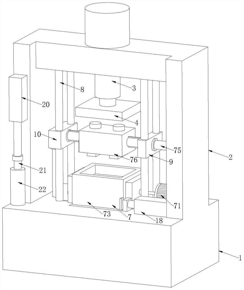
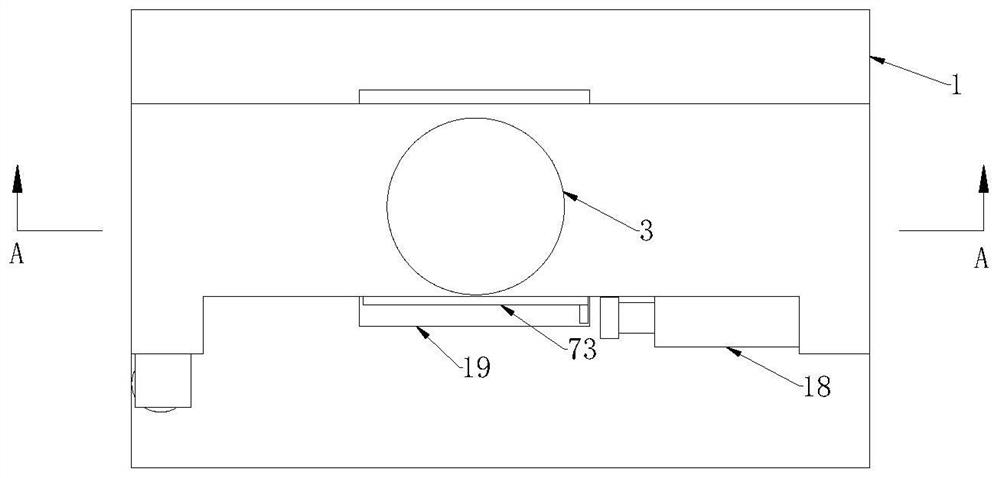
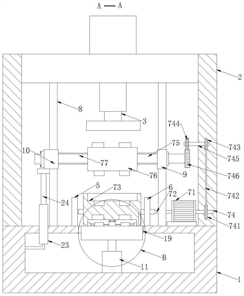
[0027] Such as Figure 1-Figure 7 As shown, a sheet metal stamping equipment according to the present invention includes a base 1, a hydraulic column 3, an upper and lower mold turning mechanism 7, a pillar 8, a first slide 9, a second slide 10, and the top of the base 1 is fixedly connected There is a support 2, the top of the support 2 is fixedly connected with a hydraulic column 3, and the output end of the hydraulic column 3 is opposite to the top of the base 1, and the output end of the hydraulic column 3 is fixedly connected with a die 4, and the top of the base 1 is pressed The bottom of the mold 4 is provided with a turning notch 19, and the top of the base 1 is respectively equipped with a first bracket 5 and a second bracket 6 near the t...


PUM


Abstract

The invention relates to the technical field of stamping equipment, in particular to sheet metal stamping equipment. The equipment comprises a base, a hydraulic column, an upper and lower die overturning mechanism, a supporting column, a first sliding seat and a second sliding seat; the top end of the base is fixedly connected with a support, the top of the support is fixedly connected with the hydraulic column, the output end of the hydraulic column is opposite to the top end of the base, and the output end of the hydraulic column is fixedly connected with a pressing die; and the upper and lower die overturning mechanism comprises a double-shaft motor, a lower die, an upper die and a driven key shaft. By arranging the upper and lower die overturning mechanism, the application range of the stamping equipment is widened, the processing efficiency is improved, and two sheet metal parts with different shapes can be processed according to needs without detaching or replacing the upper die and the lower die. By arranging the upper die and the lower die which are convenient to detach, the use range of the stamping equipment is further widened, and the labor intensity of workers is reduced.

Description

technical field [0001] The invention relates to the technical field of stamping equipment, in particular to a sheet metal stamping equipment. Background technique [0002] Stamping equipment relies on presses and molds to apply external forces to plates, strips, pipes, and profiles to cause plastic deformation or separation, thereby obtaining workpieces of required shape and size. [0003] Existing sheet metal stamping equipment requires upper and lower dies to be used together, and the shapes of the upper and lower dies are fixed. Therefore, the same set of upper and lower dies can only process sheet metal parts of the same shape. When processing sheet metal parts of other shapes, it is necessary to replace a new set of upper and lower molds. In the production process, sometimes it is necessary to alternately process two kinds of sheet metal parts with different shapes. At this time, it is necessary to switch frequently between the two stamping forms. The existing stamping...

Claims


Application Information

Patent Timeline
Patent Type & Authority Applications(China)
IPC IPC(8): B21D22/02B21D37/06B21D37/14
CPCB21D22/02B21D37/06B21D37/14
Inventor 赵海东徐泽南
Owner 赵海东
Why Eureka
Try Eureka