EPB gap adjustment method, system and vehicle with motor self-adaptive function

A clearance adjustment method and clearance adjustment technology, applied in the direction of brakes, etc., can solve the problems of prone to errors, consuming a lot of time and energy, and high testing costs, avoiding brake failure or locking, simplifying the research and development process, and ensuring safety. sexual effect

Active Publication Date: 2022-04-05
KUNTAI VEHICLE SYST CHANGZHOU CO LTD
View PDF5 Cites 0 Cited by
  • Summary
  • Abstract
  • Description
  • Claims
  • Application Information

AI Technical Summary

Problems solved by technology

[0005] This method determines the motion law and position state of the motor through the current, voltage and real-time speed of the motor, so as to control the positional relationship between the friction plate and the brake disc through the motor to ensure the automatic adjustment of the gap between the friction plate and the brake disc. , this method needs to measure and calculate the target current of the motor in the process of motor drive braking and release, and then determine the state of the motor through real-time detection. However, the determination of the target current needs to be completed through multiple tests, the calibration process is complicated, and the test cost At the same time, the target current of different types of motors is different, and it often takes a lot of time and energy to test one by one. In addition, especially in the braking state of the car, the road conditions, braking time, and braking mode of the vehicle are different. Objective factors such as differences will also have a certain impact on the target current. A single target current cannot adapt to the requirements of the motor in different states, which is prone to errors and affects the braking effect of the car.

Method used

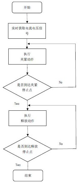
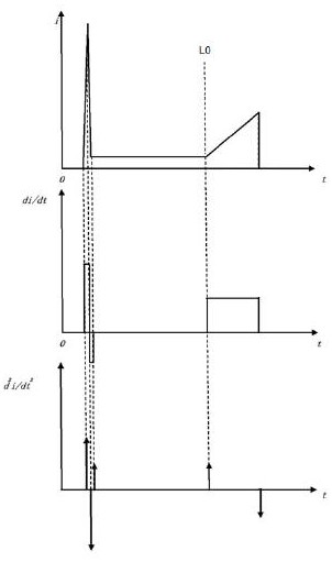
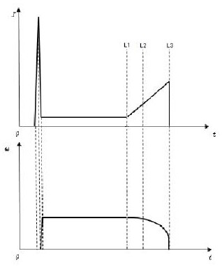

Image

  • EPB gap adjustment method, system and vehicle with motor self-adaptive function
  • EPB gap adjustment method, system and vehicle with motor self-adaptive function
  • EPB gap adjustment method, system and vehicle with motor self-adaptive function

Examples


Embodiment Construction

[0043] In order to make the objects, advantages and features of the present invention more clearly and in detail, the following non-limiting descriptions of preferred embodiments will be illustrated and explained. This embodiment is only a typical example of applying the technical solution of the present invention, and any technical solution formed by equivalent replacement or equivalent transformation falls within the protection scope of the present invention.

[0044] At the same time, it is stated that in the description of the scheme, it needs to be explained that the terms "center", "upper", "lower", "left", "right", "front", "rear", "inner", "outer" The orientation or positional relationship indicated by etc. is based on the orientation or positional relationship shown in the drawings, and is only for the convenience of description and simplification of description, rather than indicating or implying that the referred device or element must have a specific orientation or ...


PUM


Abstract

The invention discloses an EPB gap adjustment method, system and automobile with motor self-adaptive function, wherein the EPB gap adjustment method with motor self-adaptive function at least includes the following steps: when the system obtains an instruction requiring EPB gap adjustment, turn on the motor , perform a braking action; obtain the current and voltage signals of the motor in real time; calculate the real-time speed of the motor according to the obtained current and voltage signals; determine the stop braking condition according to the real-time speed and current of the motor, and the stop braking condition includes at least the first stop The braking condition and the second stopping braking condition, when the first stopping braking condition and the second stopping braking condition are met at the same time, control the motor to drive the stopping braking and start the release action. Compared with the existing method, this solution has more flexibility, can adapt to the needs of different environments, and simultaneously simplifies the research and development process and cost of the EPB system.

Description

technical field [0001] The invention relates to the technical field of vehicle control, in particular to an EPB gap adjustment method, system and automobile with motor self-adaptive function. Background technique [0002] At present, the electronic parking system (EPB for short) is generally used in vehicles to complete the parking brake of the vehicle. During the life cycle of the vehicle, the friction plate will continue to wear out with the increase in the number of braking. Failure to perform a parking maneuver will result in prolonged braking times, which can lead to safety concerns. Therefore, the EPB system needs to have the function of automatic gap adjustment, so that the distance between the friction plate and the brake disc is always kept at an appropriate distance. [0003] The current technology mainly determines the state of the motor by calibrating the target current. First, it is necessary to measure the target current for the motor to drive and stop braking...

Claims


Application Information

Patent Timeline
Patent Type & Authority Patents(China)
IPC IPC(8): B60T8/172B60T8/171B60T8/1755
CPCB60T8/172B60T8/171B60T8/17551
Inventor 陈晨肖夏宏上官晓阳尤梦月葛旭峰
Owner KUNTAI VEHICLE SYST CHANGZHOU CO LTD
Why Eureka
Try Eureka