

Testing device and method capable of measuring heat conductivity coefficient of expansive soil body in hydration process
A technology of thermal conductivity and expansive soil, which is applied in the field of expansive soil thermal conductivity testing devices, can solve the problems of inaccurate thermal conductivity measurement results and the inability to realize continuous monitoring of soil thermal conductivity, so as to achieve strong practicability and avoid unloading. Bouncing, increasing the effect of accuracy
Pending Publication Date: 2022-01-18
CENT SOUTH UNIV
View PDF13 Cites 0 Cited by
- Summary
- Abstract
- Description
- Claims
- Application Information
AI Technical Summary
Problems solved by technology
However, these methods have two shortcomings: (1) For highly expansive soils (such as bentonite materials), once the soil sample is taken out, it will rebound after unl
Method used
View moreImage
Smart ImageViewing Examples

Examples
 PUM
 Abstract
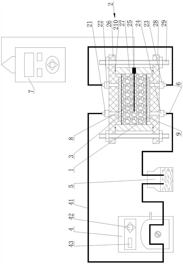
The invention discloses a testing device and method capable of measuring the heat conductivity coefficient of expansive soil in the hydration process. The device comprises a loading tank, a water supply system and a thermal characteristic analysis system, the loading tank comprises a tank body and permeable stones embedded in the top and the bottom of the inner side of the tank body, a soil sample is packaged in the tank body between the permeable stones, ,an upper water inlet valve and an upper water outlet valve are arranged at the top of the tank body, a lower water inlet valve and a lower water outlet valve are arranged at the bottom of the tank body, an insertion hole is formed in the side wall of the tank body, the water supply system comprises a peristaltic pump and a liquid containing bottle, the upper water inlet valve is communicated with the liquid containing bottle through a pump pipe of the peristaltic pump, the upper water outlet valve is communicated with the lower water inlet valve through a liquid guide pipe, and the lower water outlet valve is communicated with the liquid containing bottle through a liquid guide pipe; and the thermal characteristic analysis system comprises a thermal characteristic analyzer and a thermal probe electrically connected with the thermal characteristic analyzer, and the thermal probe is inserted into the soil sample in the tank body along the insertion hole. The hydration process can be realized under the condition that the soil sample is not taken out, and the continuous measurement of the heat conductivity coefficient in the hydration process can be realized.
Description
technical field [0001] The invention relates to the field of thermal conductivity testing devices for expansive soils, in particular to a test device and method capable of measuring the thermal conductivity of expansive soils during the hydration process. Background technique [0002] The deep geological disposal of high-level radioactive waste refers to embedding the high-level radioactive waste in solid form in the geological body 500-1000m underground, that is, digging a shaft through the surface to the deep part, digging a horizontal tunnel from the bottom of the shaft, and then digging a horizontal tunnel in the horizontal tunnel. Shafts or branch tunnels, as waste storage places, are finally sealed, so that they can be isolated from the human living environment for a long time (at least 10,000 years). These tunnels and shafts constitute the underground repository. [0003] The deep geological repository for high-level radioactive waste generally adopts a "multiple bar...
Claims
Login to View More Application Information
Patent Timeline
 IPC IPC(8): G01N25/16
CPCG01N25/16
Inventor倪雪倩张召张升
OwnerCENT SOUTH UNIV