
Multi-angle photogrammetry device with light supplementing function

A photogrammetry, multi-angle technology, applied in the field of multi-angle photogrammetry devices, can solve the problems of large adjustment error, time-consuming and laborious, and achieve the effect of improving work efficiency and avoiding damage

Active Publication Date: 2022-01-18
HUIBO NEW MATERIAL CO LTD
View PDF10 Cites 0 Cited by
  • Summary
  • Abstract
  • Description
  • Claims
  • Application Information

AI Technical Summary

Problems solved by technology

[0004] The present invention provides a multi-angle photogrammetry device with supplementary light function, aiming to solve the problems of manual adjustment of the existing device, which is time-consuming and labor-intensive, and the adjustment error is relatively large

Method used


Image

  • Multi-angle photogrammetry device with light supplementing function
  • Multi-angle photogrammetry device with light supplementing function
  • Multi-angle photogrammetry device with light supplementing function

Examples


Embodiment 1

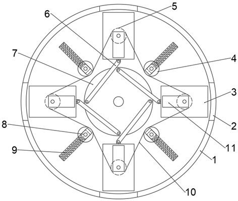
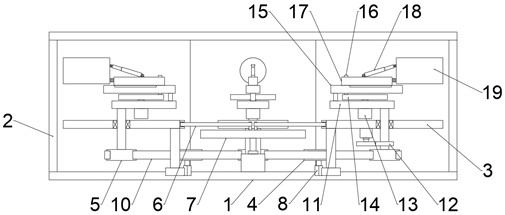
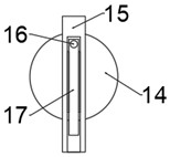
[0037] An embodiment of the present invention provides a multi-angle photogrammetry device with a supplementary light function, such as Figure 1-3 shown, including:

[0038] The photographic module 19 is a photographic device in the prior art, including a lens, a host, etc.;

[0039] The installation unit is used to install the camera module 19, and the installation unit includes a housing 1, a first installation plate 3, a second installation plate 11, a main pulley 5, a slave pulley 4, a spring 9 and a driving mechanism;

[0040] The housing 1 is provided with a plurality of first mounting plates 3 at intervals in the circumferential direction. The housing 1 is preferably circular. The first mounting plates 3 are slidably connected to the housing 1. Preferably, a slider is fixed on the first mounting plate 3. , the casing 1 is provided with a chute for sliding connection of the slider, the side wall of the casing 1 is provided with a side hole 2 for the movement of the fir...

Embodiment 2

[0046] This embodiment is on the basis of embodiment 1, as Figure 4 As shown, a heat dissipation unit is also included for blowing and dissipating heat from the camera module 19. The heat dissipation unit includes a fan 20 and a dome cover 21. The dome cover 21 is installed on the first mounting plate 3 and is located at Below the camera module 19, the air outlet of the blower fan 20 communicates with the inner cavity of the dome cover 21, and the dome cover 21 is evenly provided with air outlet holes. A dust-proof net is provided, and the blower fan 20 sucks the air into the dome cover 21 and sprays it out from the air outlet. The setting of the dome cover 21 can expand the air outlet angle and range, and improve the heat dissipation efficiency.

Embodiment 3

[0048] This embodiment is on the basis of embodiment 2, as Figure 5-6 As shown, the spherical cap 21 is rotatably connected with the first mounting plate 3, and a ring 22 is fixed on the spherical cap 21, and the circular ring 22 is preferably integrally formed with the spherical cap 21. A plurality of support plates 23 are fixed at intervals in the circumferential direction, and the radial angle between the support plates 23 and the ring 22 is provided, preferably 30-45 degrees. A branch pipe 24 is connected, and the mouth of the branch pipe 24 faces the support plate 23. When the fan 20 is working, the wind blows from the branch pipe 24 to the support plate 23, and the support plate 23 drives the spherical cover 21 to rotate, thereby forming a whirlwind through the air outlet. , to further expand the heat dissipation range and improve the heat dissipation efficiency.


PUM


Abstract

The invention is applicable to the technical field of photogrammetry, and provides a multi-angle photogrammetry device with a light supplementing function. The device comprises photographing modules; and a mounting unit which is used for mounting the photographing modules, wherein the mounting unit comprises a shell, a first mounting plate, a second mounting plate, a driving belt wheel, a driven belt wheel, a spring and a driving mechanism. The device further comprises a light supplementing unit. The photographing modules and the mounting unit are arranged, so during work, the photographing modules on multiple first mounting plates are driven by the driving mechanism to move out of the shell, and the multiple photographing modules conduct photogrammetry work synchronously at multiple angles; a power mechanism drives one main belt wheel to rotate, and under the effect of a belt, the main belt wheel is driven by the power mechanism to rotate, the main belt wheel drives the second mounting plate to rotate through the rotating shaft, and the angles of the multiple photographing modules are synchronously adjusted, so the working efficiency is improved; The light supplementing unit is arranged, so the angle of the mounting rod can be adjusted through the adjusting mechanism, then the angle of the light guide plate is adjusted, and the light supplementing angle is further adjusted.

Description

technical field [0001] The invention belongs to the technical field of photogrammetry, and in particular relates to a multi-angle photogrammetry device with a supplementary light function. Background technique [0002] Photogrammetry is a photo taken by an optical camera, which is processed to obtain the shape, size, position, characteristics and relationship of the object being photographed; [0003] Existing photogrammetry devices are generally equipped with multiple lenses to meet multi-angle measurement. When adjusting the lens angles, manually adjusting each lens is not only time-consuming and laborious, but also has large adjustment errors, which affects the efficiency of measurement work. Contents of the invention [0004] The invention provides a multi-angle photogrammetry device with a light supplement function, aiming to solve the problems of manual adjustment of the existing device, which is time-consuming and laborious, and has large adjustment errors. [0005...

Claims


Application Information

Patent Timeline
Patent Type & Authority Applications(China)
IPC IPC(8): G03B15/00G03B15/02G03B17/56
CPCG03B15/00G03B15/02G03B17/56G03B17/561
Inventor 杨建辉樊泽贵
Owner HUIBO NEW MATERIAL CO LTD
Learn More