
Switch cabinet arcing pressure relief device

A technology of pressure relief device and cabinet arc, which is applied in the cooling/ventilation of substation/switchgear, electric switch, details of substation/switch arrangement, etc., to achieve the effect of improving safety assurance

Pending Publication Date: 2022-01-18
XJ ELECTRIC +1
View PDF0 Cites 1 Cited by
  • Summary
  • Abstract
  • Description
  • Claims
  • Application Information

AI Technical Summary

Problems solved by technology

"Most of the switchgear cabinets on the market currently have flat pressure relief covers that cannot meet this requirement, so the switchgear arcing pressure relief device came into being

Method used


Image

  • Switch cabinet arcing pressure relief device
  • Switch cabinet arcing pressure relief device
  • Switch cabinet arcing pressure relief device

Examples


Embodiment Construction

[0038] In order to make the object, technical solution and advantages of the present invention clearer, the present invention will be further described in detail below in combination with specific embodiments and with reference to the accompanying drawings. It should be understood that these descriptions are exemplary only, and are not intended to limit the scope of the present invention. Also, in the following description, descriptions of well-known structures and techniques are omitted to avoid unnecessarily obscuring the concept of the present invention.

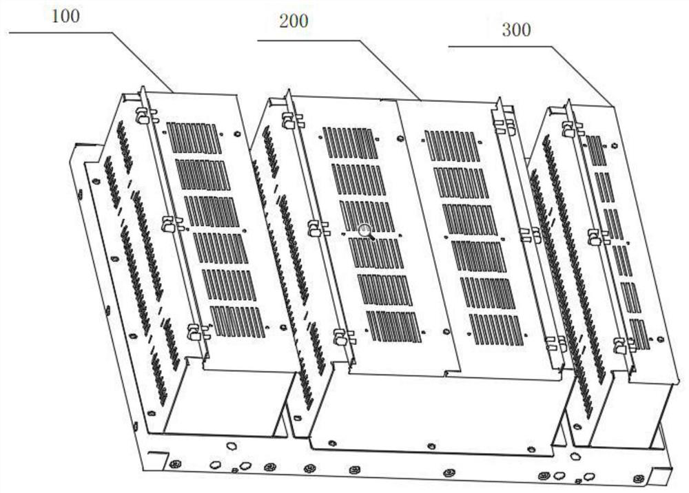
[0039] The invention discloses a switchgear arcing pressure relief device, such as figure 1 As shown, a switch cabinet of the present invention is equipped with three standard pressure relief devices (800mm wide): circuit breaker chamber pressure relief device 100, busbar chamber pressure relief device 200 (without fan) and cable chamber pressure relief device 300 (1450mm for deep cabinets).

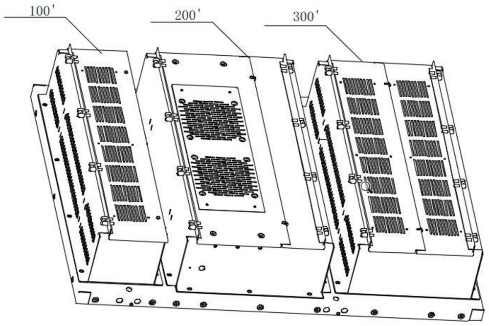
[0040] Such as figure 2 ...


PUM


Abstract

A switch cabinet arcing pressure relief device comprises a breaker chamber pressure relief device, a bus chamber pressure relief device and a cable chamber pressure relief device. The pressure relief device comprises a pressure relief cover, a pressure relief frame, an arc-blocking honeycomb plate, a pressure relief screen plate, a hinge and a nylon bolt; one side of the pressure relief cover is connected to the pressure relief frame through a hinge, and the other side of the pressure relief cover is connected to the pressure relief frame through a nylon bolt. The pressure relief frame comprises a pressure relief frame front vertical plate, a pressure relief frame side vertical plate and a pressure relief frame reinforcing beam; the arc blocking honeycomb plate is arranged in the pressure relief frame and below the pressure relief screen plate; and the pressure relief screen plate is arranged in the pressure relief frame and above the arc-blocking honeycomb plate. When an internal fault arc is generated in the switch cabinet, the pressure release device can be reliably opened, the pressure release direction avoids an inspection tour channel and other equipment, the arcing device can be suitable for switch cabinets with different depths and widths, the number of fans can be increased or decreased to enhance ventilation, and the arcing device is safe and reliable and is applied to effective pressure release of the switch cabinet.

Description

technical field [0001] The invention relates to the field of electrical technology, in particular to an arcing and pressure relief device for a switch cabinet. Background technique [0002] Switchgear is a kind of electrical equipment for opening and closing, control and protection in the process of power generation, transmission, distribution and power conversion in the power system. During the operation of the switchgear, for some reason, the line short-circuit fault is caused. Under the action of a huge short-circuit current, high-temperature and high-pressure gas will be generated instantaneously. If these high-temperature and high-pressure gases cannot be effectively released in a very short time, it will be like a self-exploding bomb. It will cause deformation of the switchgear and cause casualties; and the document "State Grid Corporation of China on Printing and Distributing Eighteen Major Power Grid Anti-Accident Measures (Revised Edition)" 12.4.1.5 clearly requires...

Claims


Application Information

Patent Timeline
Patent Type & Authority Applications(China)
IPC IPC(8): H02B1/30H02B1/38H02B1/56H01H9/30
CPCH02B1/30H02B1/38H02B1/565H01H9/30
Inventor 李孟达郭相仲张桂如张伟鹏董会平朱凤玲王皓翔谢春阳张香芍高颖旭李振兴刘巧愿杜永平
Owner XJ ELECTRIC
Learn More