Eye phototherapy instrument

A phototherapy device and eye technology, applied in the field of phototherapy, can solve the problems of poor treatment effect, eye discomfort, scattered light treatment, etc., and achieve the effects of improving eye soreness, relieving dark circles, and promoting blood circulation.

Pending Publication Date: 2022-01-21
GUAN YEOLIGHT TECH CO LTD
View PDF0 Cites 0 Cited by
  • Summary
  • Abstract
  • Description
  • Claims
  • Application Information

AI Technical Summary

Problems solved by technology

[0003] In the prior art, the treatment light emitted by the eye phototherapy instrument is relatively scattered, the treatment effect is poor, and it is easy to directly hit the eyelid or eyeball, causing eye discomfort and affecting eye health

Method used


Image

  • Eye phototherapy instrument
  • Eye phototherapy instrument
  • Eye phototherapy instrument

Examples


Embodiment 2

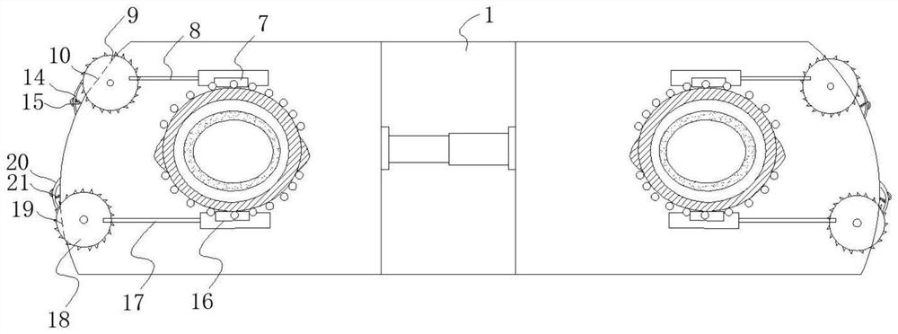
[0065] On the basis of Embodiment 1, in this embodiment, the installation sleeve 3 is an elastic structure, and the installation sleeve 3 has a first side wall close to the upper part of the human eye; the first side wall is installed with a first adjustment components;

[0066] The first adjustment assembly includes:

[0067] The first pressing plate 7 is installed on the first side wall;

[0068] A first connecting rod 8, one end of which is fixedly connected to the first pressing plate 7;

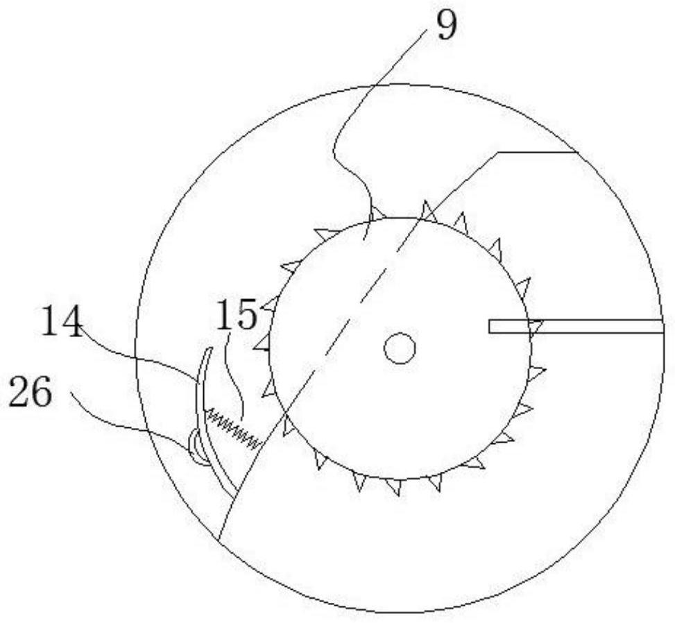
[0069] The first adjusting gear 9 is rotatably mounted on the body 1 and fixedly connected with the other end of the first connecting rod 8;

[0070] Wherein, the first connecting rod 8 is arranged radially along the first adjusting gear 9, the axial direction of the first connecting rod 8 forms an acute angle with the first direction, and the first direction is perpendicular to the first pressing plate 7.

[0071] Working principle: As shown in Figure 2, when the first adjusting gea...

Embodiment 3

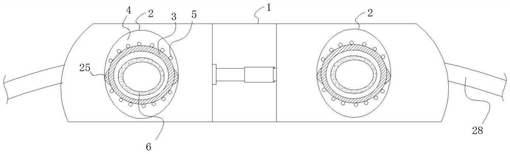
[0099] On the basis of embodiment 1, in this embodiment, as Figure 5 As shown, the tank body 2 is provided with two; the body 1 has a connecting portion 11 and two mounting portions 12 arranged on one side of the connecting portion 11; there is a deformation interval 13 between the two mounting portions 12 , the tank body 2 is disposed on the mounting portion 12 .

[0100] Specifically, since there is a deformation interval 13 between the two installation parts 12, the deformation interval 13 of the two installation parts 12 can be adjusted according to the distance between the eyes of different patients. It avoids that the treatment light source cannot be accurately injected into the lesion area due to the difference in the distance between the eyes of different patients, and improves the treatment effect.

[0101] In a preferred embodiment, a position adjustment mechanism for adjusting the deformation interval is installed between the two installation parts 12 .

[0102] ...


PUM


Abstract

The application provides an eye phototherapy instrument. The eye phototherapy instrument comprises a body; a groove body corresponding to human eyes is formed on one side of the body, and a treatment device is installed in the groove body; the treatment device comprises an installation sleeve and a light shield; the installation sleeve is arranged in the groove body; an irradiation channel is formed between the inner side wall of the groove body and the outer side wall of the installation sleeve; a plurality of light sources are arranged in the irradiation channel, and the light sources are used for emitting treatment light; and the light shield is coaxially arranged in the installation sleeve and is used for shielding the treatment light incident to eyeballs. According to the eye phototherapy instrument provided by the application, an annular treatment region can be formed, so that the treatment light is prevented from being incident to the eyeballs; and meanwhile, a hot compress effect is taken on the region, so that blood circulation of the eyes is further promoted, dark circles are relieved, and soreness and swelling of the eyes are improved.

Description

technical field [0001] The present disclosure generally relates to the technical field of phototherapy, and specifically relates to an eye phototherapy instrument. Background technique [0002] The eye phototherapy instrument is mainly used to irradiate the eyes with therapeutic light, which can play the role of auxiliary treatment; [0003] In the prior art, the treatment light emitted by the eye phototherapy apparatus is relatively scattered, the treatment effect is poor, and it is easy to directly hit the eyelid or eyeball, causing eye discomfort and affecting eye health. Contents of the invention [0004] In view of the above-mentioned defects or deficiencies in the prior art, it is desired to provide an eye phototherapy device that can solve the above-mentioned technical problems. [0005] The present application provides an eye phototherapy instrument, comprising: a body; one side of the body is provided with a tank corresponding to the human eye, and a treatment de...

Claims


Application Information

Patent Timeline
IPC IPC(8): A61F9/00A61F9/04A61N5/02A61N5/06A61F7/02
CPCA61F9/00A61F9/045A61F7/02A61N5/022A61N5/0625A61F2007/0004A61N2005/0648A61N2005/0651A61N2005/0653Y02A50/30
Inventor 谢静胡永岚张国辉李栋栋
Owner GUAN YEOLIGHT TECH CO LTD
Why Eureka
Try Eureka