Arm directional supporting device for orthopedic department surgery

A supporting device and a technique for surgery, which are applied in the fields of surgery, operating table, medical science, etc., can solve the problems of surgical errors, large size of the hand rest, and the inability of the arm to limit the position of the hand rest.

Pending Publication Date: 2022-01-21
廖德祯
View PDF10 Cites 0 Cited by
  • Summary
  • Abstract
  • Description
  • Claims
  • Application Information

AI Technical Summary

Problems solved by technology

[0004] In order to overcome the disadvantages that the handrest is too large, which hinders the doctor from performing surgery, and the handrest cannot limit the position of the arm, and the patient moves the arm carelessly due to pain, which may easily lead to surgical mistakes. The purpose of the present invention is to provide a convenient Arm directional support device for orthopedic department surgery that fixes the arm, does not hinder the doctor's operation, and can limit the position of the arm

Method used


Image

  • Arm directional supporting device for orthopedic department surgery
  • Arm directional supporting device for orthopedic department surgery
  • Arm directional supporting device for orthopedic department surgery

Examples


Embodiment 1

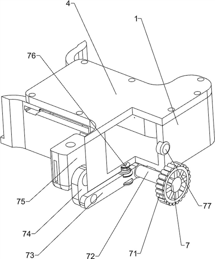
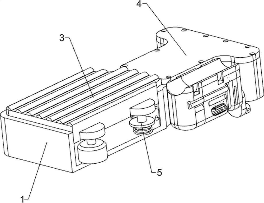
[0037] An arm directional support device for orthopedic department surgery, such as Figure 1-Figure 5 As shown, it includes a fixed bed frame 1, a positioning base frame 2, a buffer base plate 3, a sponge fixing plate 4, a buffer column 5, a reversing mechanism 7 and an arm positioning mechanism 8, and the upper part of the positioning base frame 2 is provided with a fixed bed frame 1, The rear of the fixed bed frame 1 is slidingly provided with a buffer base plate 3, the upper side of the front of the fixed bed frame 1 is provided with a sponge fixing plate 4, and the rear side of the inner bottom of the fixed bed frame 1 and the interior of the buffer base plate 3 are evenly spaced with buffer columns 5. The fixed bed frame 1 is provided with a reversing mechanism 7, and the reversing mechanism 7 is provided with an arm positioning mechanism 8.

[0038]The reversing mechanism 7 includes a reversing dial 71, a reversing column 72, an orientation bar 73, a positioning block 7...

Embodiment 2

[0042] On the basis of Example 1, such as Figure 6-Figure 11 As shown, a moving mechanism 9 is also included, and the moving mechanism 9 includes a servo motor 91, a drive shaft 92, a first transmission assembly 93, a driving screw 94, an orientation cylinder 95, an extension button 96 and a retraction button 97. The bottom of the support base 81 is fixedly connected with a servo motor 91, the output shaft of the servo motor 91 is connected with a drive shaft 92, and the front side of the bottom of the support base 81 is rotated to be provided with a driving screw 94, and the front circumference of the drive screw 94 is connected to the drive shaft. The middle part of the shaft 92 is connected with the first transmission assembly 93 in the circumferential direction, and the inner surface of the mobile base 82 is fixedly connected with the orientation cylinder 95, and the orientation cylinder 95 is set on the driving screw 94, and the orientation cylinder 95 is screwed to the d...

Embodiment 3

[0047] On the basis of embodiment 1 and embodiment 2, such as Figure 12-Figure 15 As shown, a fixed mechanism 11 is also included. The fixed mechanism 11 includes a third transmission assembly 111, a marble rotating shaft 112, a second reversing gear 113 and a fixed gear ring 114. The upper side of the upper part is all rotatably provided with a marble rotating shaft 112, and the third transmission assembly 111 is connected between the outer circumference of the marble rotating shaft 112 and the outer circumference of the drive screw mandrel 94, and the inner circumferential rotation of the pin rotating shaft 112 is provided with a second reversing gear 113 , the upper part of the steering support base 81 and the upper part of the mobile base 82 are provided with a fixed gear ring 114 , and the fixed gear ring 114 meshes with the second reversing gear 113 .

[0048] Also includes an injection mechanism 12, the injection mechanism 12 includes a hinged connecting plate 121, a p...


PUM


Abstract

The invention relates to a supporting device, in particular to an arm directional supporting device for orthopedic department surgery. According to the arm directional supporting device for the orthopedic department surgery, people can conveniently fix arms, surgical operation of doctors is not hindered, and the arms can be limited. An arm directional supporting device for orthopedic department surgery comprises a positioning bottom frame, wherein a fixed bed frame is arranged on the positioning bottom frame; a buffer bottom plate which is mounted on the fixed bed frame in a sliding manner; a sponge fixing plate which is mounted on the fixed bed frame. Through cooperation of the reversing mechanism and the arm positioning mechanism, the left-right position of the reversing base can be adjusted by twisting a reversing rotary table according to requirements, then the movable base is pulled to move backwards to a proper position, and people can place the left hand between the steering supporting base and the movable base, so that the arms of people can be conveniently fixed;the surgical operation of a doctor is not hindered.

Description

technical field [0001] The invention relates to a support device, in particular to an arm directional support device for orthopedic department operations. Background technique [0002] When an orthopedic patient's arm undergoes orthopedic surgery, the arm is easy to move, and the patient's arm is generally fixed in advance. At present, most people use the hand rest to fix their arms. Due to the large size of the hand rest and the limited space for the surgical assistant to stand, it hinders the doctor from performing surgery, and the hand rest cannot limit the position of the arm. It is painful to move the arm, which can easily lead to surgical errors. [0003] How to design an arm directional support device for orthopedic department surgery that is convenient for people to fix the arm, does not hinder the doctor's operation, and can limit the arm, so as to solve the problems in the prior art. Contents of the invention [0004] In order to overcome the disadvantages that...

Claims


Application Information

Patent Timeline
Patent Type & Authority Applications(China)
IPC IPC(8): A61G13/12
CPCA61G13/1235A61G13/128
Inventor 廖德祯
Owner 廖德祯
Why Eureka
Try Eureka