Method for improving edge profile of thin strip steel
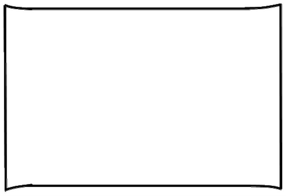
A thin strip and profile technology is applied in the field of production control for improving the edge profile of continuous casting thin strip, which can solve the problems such as the inability to solve the edge profile of thin strip casting, and achieves solutions such as poor profile, poor profile, etc. Improve product quality and improve the effect of plate profile
- Summary
- Abstract
- Description
- Claims
- Application Information
AI Technical Summary
Problems solved by technology
Method used
Image
Examples
Embodiment 1
[0034] Continuous casting of thin strip steel with a width of 1690mm, real-time detection of continuous casting speed v in the process of continuous casting of thin strip steel 0 It is 70m / min, and the thickness of the edge of the strip is detected by a thickness detector.
[0035] Get edge position L 1 at 59mm, width range B 1 Thickness extremum h within 26mm 1 is 1.45mm.
[0036] Get the secondary edge position L 2 at 117mm, width range B 2 Thickness extremum h within 19mm 2 is 1.41mm.
[0037] Get strip width center L 3 (1 / 2 of strip width 1690mm) is 845mm, width range B 3 The thickness extremum h within 38mm is 1.8mm.
[0038] Combining the width of the thin strip and the casting speed v 0 , select the empirical parameter a of thickness deviation as 9, and pass the formula:
[0039]
[0040] The calculated and returned updated continuous casting speed value v is 70.33m / min for real-time speed feedback of continuous casting speed.
[0041] Through fast feedba...
Embodiment 2
[0043] Continuous casting of thin strip steel with a width of 1340mm, real-time detection of continuous casting speed v in the process of continuous casting of thin strip steel 0 It is 42m / min, and the thickness of the edge of the strip is detected by a thickness detector.
[0044] Get edge position L 1 at 32mm, width range B 1 Thickness extremum h within 19mm 1 is 1.39mm.
[0045]Get the secondary edge position L 2 at 99mm, width range B 2 Thickness extremum h within 16mm 2 is 1.36mm.
[0046] Get strip width center L 3 (1 / 2 of strip width 1340mm) at 670mm, width range B 3 The thickness extremum h within 31 mm is 1.6 mm.
[0047] Combining the width of the thin strip and the casting speed v 0 , select the thickness deviation parameter a to be 16, and pass the formula:
[0048]
[0049] The calculated and returned updated continuous casting speed value v is 42.11m / min for real-time speed feedback of continuous casting speed.
[0050] Through fast feedback on the...
Embodiment 3
[0052] Continuous casting of 950mm wide thin strip steel, real-time detection of continuous casting speed v in the process of continuous casting of thin strip steel 0 It is 96m / min, and the thickness of the edge of the strip is detected by a thickness detector.
[0053] Get edge position L 1 at 24mm, width range B 1 Thickness extremum h within 9mm 1 is 1.27mm.
[0054] Get the secondary edge position L 2 at 83mm, width range B 2 Thickness extremum h within 12mm 2 is 1.26mm.
[0055] Get strip width center L 3 (1 / 2 of the strip width 950mm) is 475mm, width range B 3 The thickness extremum h within 22 mm is 1.4 mm.
[0056] Combining the width of the thin strip and the casting speed v 0 , select the thickness deviation parameter a to be 1.7, and pass the formula:
[0057]
[0058] The returned velocity value v is calculated to be 96.21m / min for real-time velocity feedback of continuous casting velocity.
[0059] Through fast feedback on the real-time continuous ca...
PUM
 Abstract
Description
Claims
Application Information
 - R&D
- Intellectual Property
- Life Sciences
- Materials
- Tech Scout
- Unparalleled Data Quality
- Higher Quality Content
- 60% Fewer Hallucinations
Browse by: Latest US Patents, China's latest patents, Technical Efficacy Thesaurus, Application Domain, Technology Topic, Popular Technical Reports.
© 2025 PatSnap. All rights reserved.Legal|Privacy policy|Modern Slavery Act Transparency Statement|Sitemap|About US| Contact US: help@patsnap.com


