
Auto darkening eye protection device

Inactive Publication Date: 2008-03-27
YANG YEA CHYI
View PDF7 Cites 0 Cited by
  • Summary
  • Abstract
  • Description
  • Claims
  • Application Information

AI Technical Summary

Benefits of technology

[0009]It is therefore an objective of the present invention to provide an auto darkening eye protection device to solve the weight, cost, thickness, strength and hazardous problems of the conventional filter and protective plate made of glass.
[0010]It is another objective of the present invention to provide an auto darkening eye protection device to solve the manufacturing, yield and cost problems caused by the dye method for filtering the light.
[0011]It is another objective of the present invention to provide an auto darkening eye protection device to solve the manufacturing, cost and quality problems caused by the conventional penetrating windows setting in the housing.

Problems solved by technology

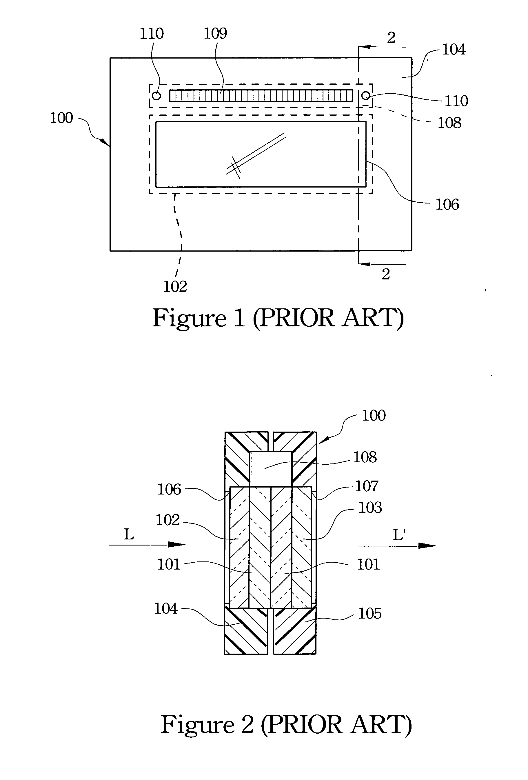
1. The glass filter 102 functions not only a substrate for filtering light but also a protection for polarizer on the liquid crystal filter 101 as the same as the protective glass 103. If the glass filter 102 is flimsy, the strength is reduced such that the glass filter 102 is too fragile. Contrarily, if the glass filter 102 is thick, the weight and thickness of the auto darkening eye protection device 100 are increased to raise the manufacturing cost.
2. Because the conventional filter 102 is made of glass and the ultraviolet and the infrared ray are shaded. Besides, there is another filter manufacturing technology that coats a film on the plastic material. However, the plastic body has lower heat resistance such that the bending and the deformation probably occur. Yet, another economic method is to use a dye on the plastic filter to filter the light, such as the U.S. Pat. No. 6,021,520. But the IR transparency of the liquid crystal filter 101 is very high. Thus, only the filter 102 shades the IR such that the dye ratio of the filter 102 must be increased. In this method, the visible light transmitting is reduced such that the luminance inside the filter device 100 becomes dark before the liquid crystal filter 101 changes into a dark state. Contrarily, decreasing the dye ratio will increase the IR transparency so the safety standards cannot be complied with. Therefore, the filter 102 using plastic material and the dye method cannot comply with the safety standard and get optimal visible light transmitting simultaneously unless increasing the thickness of the filter in the U.S. Pat. No. 6,021,520.
3. In order to fabricate the filter 102 and the protective glass 103, the penetrating window 106 and the penetrating window 107 are respectively defined in the first housing 104 and the second housing 105. By this method, the manufacturing and the cost are raised, and the worse sealing between the filter 102 and the penetrating windows 106 and 107 will affect the polarization of the polarizer in the liquid crystal filter 101 because moisture and air can enter. As a result, the utility period is shortened.

Method used


Image

  • Auto darkening eye protection device
  • Auto darkening eye protection device
  • Auto darkening eye protection device

Examples


first embodiment

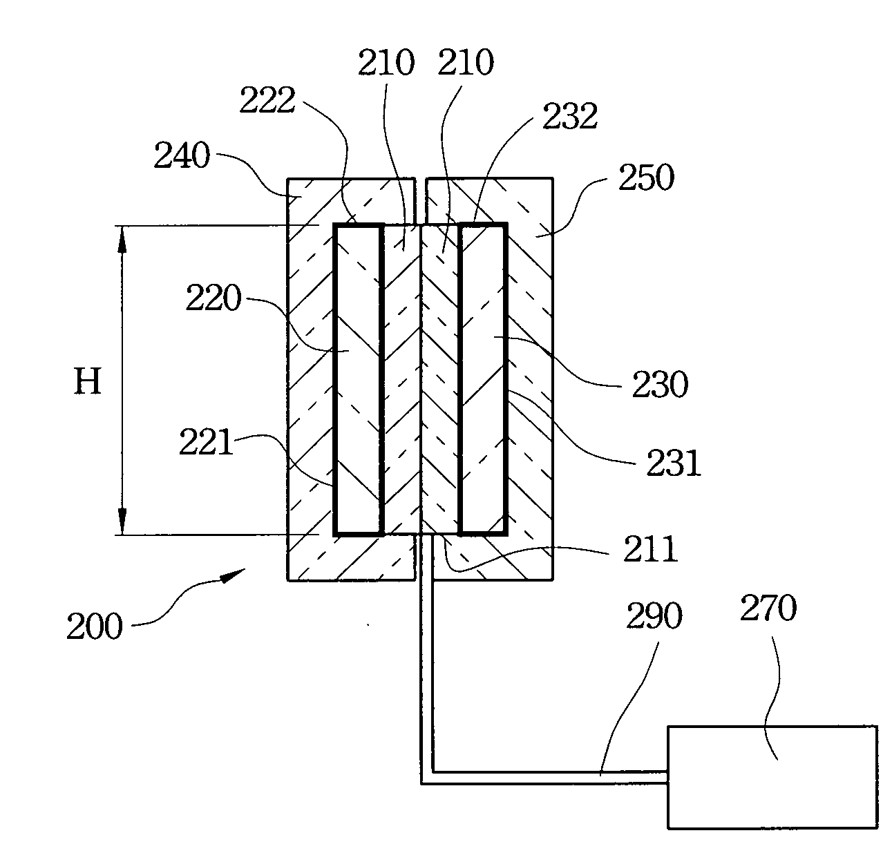
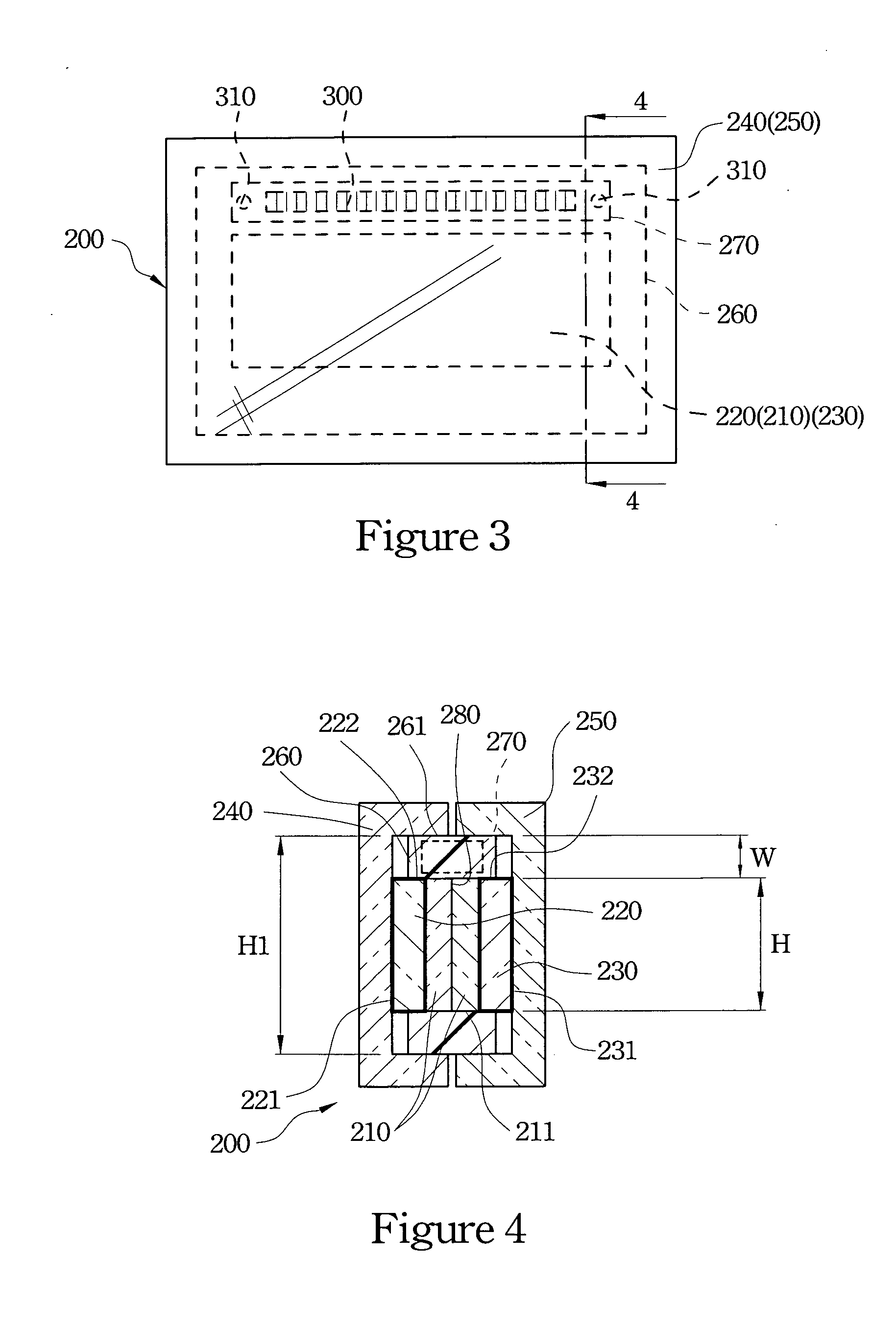
[0044]The first housing 240 is made of plastic material with light-transmitting and is hermetically covered in the exterior of the first filter 220. In the first embodiment, the section of the first housing 240 is an inverse U type to further cover a periphery 261 of the covering layer 260.

[0045]The second housing 250 is made of plastic material with light-transmitting and is hermetically covered in the exterior of the second filter 230. In the first embodiment, the section of the second housing 250 is an inverse U type to further cover a periphery 261 of the covering layer 260.

[0046]The control circuit 270 is electrically connected with the liquid crystal filters 210 to control the liquid crystal filters 210.

[0047]In the first embodiment, a height H (the viewing area of the body 200) of the liquid crystal filter 210 is less than a height H1 (the lens window of the body 200) of the covering layer 260. Thus, setting the covering layer 260 is to cover the other areas except the viewin...

second embodiment

[0054]Refer to the FIG. 5. FIG. 5 illustrates a sectional view of the auto darkening eye protection device of the present invention. The body 200 includes a first filter 220′, two liquid crystal filters 210, a second filter 230 with coat 231 or dyeing, a first housing 240, a covering layer 260 and a control circuit 270.

[0055]The fabrication and structure of the liquid crystal filters 210, the second filter 230, the first housing 240, the covering layer 260 and the control circuit 270 in the second embodiment are the same as the fabrication and structure in the first embodiment of FIG. 4. Thus, there is no more detailed description in the following.

[0056]The first filter 220′ in the second embodiment is a light-transparent plate made of plastic material with coat 221 or dyeing. In this embodiment, the first filter 220′ is capable of filtering the light and has the same function as the housing.

[0057]In this way, the liquid crystal filters 210 can also be protected by the first filter ...

third embodiment

[0058]Refer to FIG. 6. FIG. 6 illustrates a sectional view of the auto darkening eye protection device of the present invention. The body 200 includes the first housing 240, the first filter 220, two liquid crystal filters 210, a second filter 230′, a covering layer 260 and a control circuit 270.

[0059]The fabrication and structure of the first housing 240, the first filter 220, the liquid crystal filters 210, the covering layer 260 and the control circuit 270 in the third embodiment are the same as the fabrication and structure in the first embodiment of FIG. 4. Thus, there is no more detailed description in the following.

[0060]The second filter 230′ in the third embodiment is a light-transparent plate made of plastic material with coat 231 or dyeing. In this embodiment, the second filter 230′ is capable of filtering the light and has the same function as the housing.

[0061]In this way, the liquid crystal filters 210 can be also protected by the first filter 220 and the second filter...


PUM


Abstract

An auto darkening eye protection device, including a first filter, a second filter, at least one liquid crystal filter and a control circuit, is provided. The first filter and the second filter are made of light-transmitting plastic and with films to shade ultraviolet (UV) and infrared (IR) rays. The liquid crystal filter is hermetically set between the first filter and the second filter to obtain better light-transmitting. Besides, the first filter and the second filter are manufactured by plastic injection molding so there are some advantages that are easy manufacturing, low cost, impact endurance, light and filmy.

Description

BACKGROUND[0001]1. Field of Invention[0002]The present invention relates to a protection device, and more particularly to a welding auto darkening eye protection device.[0003]2. Description of Related Art[0004]Refer to FIG. 1 and FIG. 2. FIG. 1 is a front view which illustrates an auto darkening filter (ADF) for welding in accordance with the prior art, and FIG. 2 is a sectional view which illustrates the auto darkening filter (ADF) for welding in accordance with the prior art. A conventional filter device 100 includes two (or single) liquid crystal filter 101 with light-transmitting, a coated glass filter 102 with light-transmitting, a protective glass 103 with light-transmitting, a first housing 104, a second housing 105, a control circuit 108, a solar cell 109 and one or more than one sensors 110. The first housing 104 and the second housing 105 are made of plastic with opacity. The control circuit 108 is located between the first housing 104 and the second housing 105. The solar...

Claims


Application Information

Patent Timeline
IPC IPC(8): G02F1/1335
CPCG02F1/133509A61F9/067
Inventor YANG, YEA-CHYI
Owner YANG YEA CHYI
Learn More