A high-speed vacuum filling and protective gas device

A technology of vacuuming and protecting gas, applied in the direction of packaging under vacuum/special atmosphere, etc., can solve the problems of reducing the service life of the sealing ring and low flexibility, and achieve the effect of ensuring quality, reducing risks, and not easy to accumulate powder

Active Publication Date: 2022-04-05
CHANGZHOU JOYO AUTOMATION EQUIP CO LTD
View PDF13 Cites 0 Cited by
  • Summary
  • Abstract
  • Description
  • Claims
  • Application Information

AI Technical Summary

Problems solved by technology

3. The sealing cylinder of the device moves up and down along the shaft of the supporting tank, and the seal between the sealing cylinder and the supporting tank shaft is sealed by a sealing ring. The up and down movement of the sealing cylinder reduces the service life of the sealing ring
4. There are strip windows on the side walls of the vacuum chamber and nitrogen filling chamber of this device, which means that the chamber must be turned to a specific angle area to complete a specific vacuuming or nitrogen filling action, and the flexibility is low
[0006] In March 2021, the Chinese invention patent 202110273226.9 disclosed a multiple-extraction packaging bag vacuum device: 1. The modified device includes a turntable, an air distribution plate, and the air distribution plate is divided into upper and lower plates. There are two vacuuming channels, the vacuuming channel is oval and L-shaped, therefore, the turntable must be turned to a specific angle area to complete the specific vacuuming, and the flexibility is low

Method used


Image

  • A high-speed vacuum filling and protective gas device
  • A high-speed vacuum filling and protective gas device
  • A high-speed vacuum filling and protective gas device

Examples


Embodiment Construction

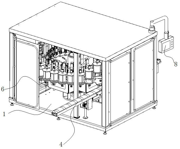
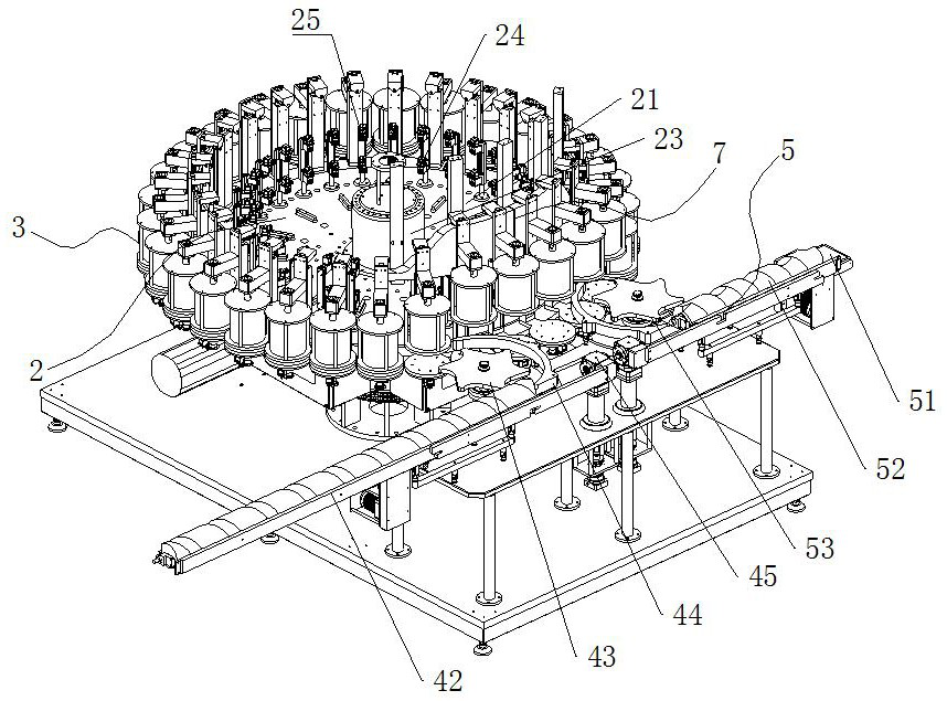
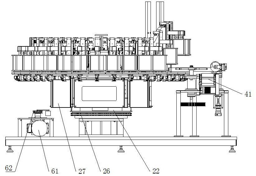
[0038] See Figure 1 to Figure 3 The present invention has a frame 1, a rotating column part 2, a vacuum cover assembly 3, a tank inlet part 4, a tank outlet part 5, a driving part 6, a lifting track 7, and a control part 8. The frame 1 is fixed on the ground; the rotating column The part 2 is rotatably arranged on the bottom frame of the frame 1; there are several vacuum cover assemblies 3, which are evenly arranged around the rotating column part 2; the tank inlet part 4 is horizontally arranged on the side of the rotating column part 2; the tank outlet part 5 It is horizontally arranged on one side of the rotating column part 2; the driving part 6 is arranged on the frame 1 and is driven and connected with the rotating column part 2; the lifting track 7 is arranged outside the rotating column part 2, next to the vacuum cover assembly 3, and fixed Under the top frame of the frame 1; the control part 8 is electrically connected and controlled with the rotating column part 2, ...


PUM


Abstract

The invention relates to the field of packaging machinery, in particular to a high-speed vacuum filling and protective gas device. It has a frame, a rotating column part, a vacuum cover assembly, a tank inlet part, a tank outlet part, a driving part, a circular track, and a control part. The frame is fixed on the ground; the rotating column part is rotatably set on the bottom frame of the frame ; There are several vacuum cover components, which are evenly arranged around the rotating column; the tank inlet part is horizontally arranged on the side of the rotating column; the tank outlet is horizontally arranged on the side of the rotating column; The internal drive is connected; the ring track is arranged around the outside of the rotating column, next to the vacuum cover assembly, and fixed under the top frame of the frame; the present invention uses a circular table to circulate, and does not need to collect, store and transfer out the jar artificially. There is no storage at intervals, and online flow production operations are possible. It is easy to operate and maintain, and can greatly improve the packaging quality.

Description

technical field [0001] The invention relates to the field of packaging machinery, in particular to a high-speed vacuum filling and protective gas device. Background technique [0002] In terms of food packaging, people are particularly concerned about the freshness of food. For food packaging, there must be a process of vacuuming and filling protective gas and packaging technology, so as to reduce the amount of residual oxygen and the shelf life of products. And effectively extend the shelf life. [0003] The existing vacuum-pumping, nitrogen-filling and seaming machines have limited canning capacity, low work efficiency, and are prone to flying powder, which can no longer meet the requirements of high-speed production lines. Due to the mechanical structure, it cannot be dedicated to the application of high-speed lines, and the amount of flying powder is higher than that of high-speed vacuum nitrogen filling equipment. [0004] Most of the existing equipment for vacuuming ...

Claims


Application Information

Patent Timeline
Patent Type & Authority Patents(China)
IPC IPC(8): B65B31/02
CPCB65B31/02
Inventor 顾杨凯陈立杨成吉扬史可可周董娟石奇敏
Owner CHANGZHOU JOYO AUTOMATION EQUIP CO LTD
Why Eureka
Try Eureka