Penetrating jointed rock mass hydraulic fracturing extension destruction device and test method
A jointed rock mass and hydraulic fracturing technology, which is applied in the direction of measuring devices, using stable tension/pressure testing material strength, instruments, etc., can solve the problem of poor hydraulic pressure monitoring accuracy, the existence of test pieces, and the inability to adapt to test pieces Specifications and other issues, to achieve the effect of convenient operation of the device, ensuring the accuracy of water pressure, and increasing practical performance
- Summary
- Abstract
- Description
- Claims
- Application Information
AI Technical Summary
Problems solved by technology
Method used
Image

Examples
Embodiment 1
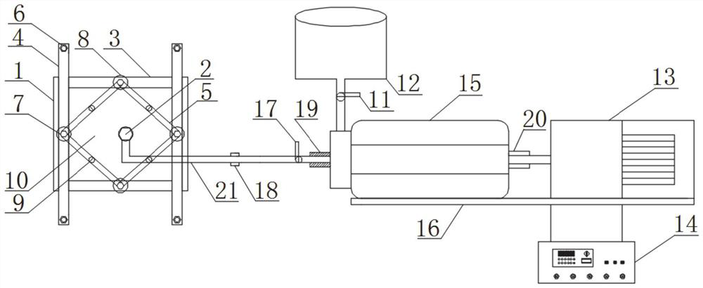
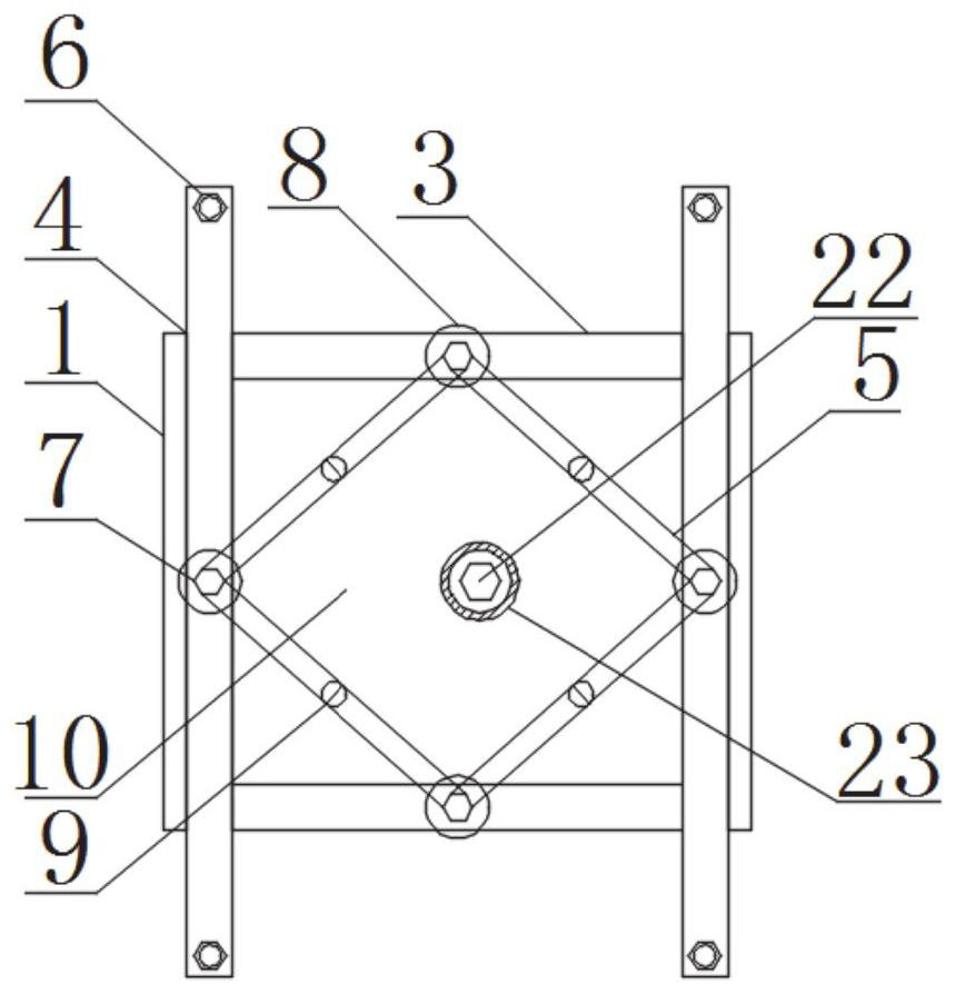
[0038] Such as Figure 1-Figure 3 As shown, this embodiment provides a typical through-joint rock hydraulic fracturing expansion and destruction device of the present disclosure, including a sealing fixture, and a water injection device that provides a set water pressure for the sealing fixture. The water outlet of the water injection device is provided with Water pressure monitoring sensor 19;
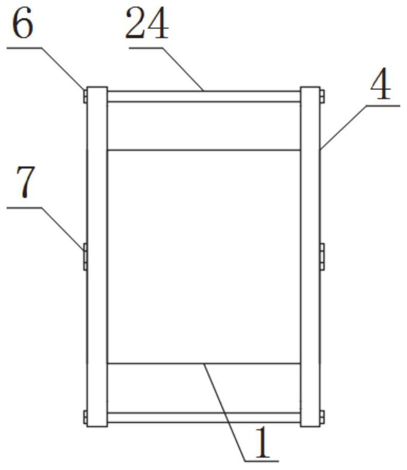
[0039] The sealing fixture comprises a bracket, and the bracket includes two symmetrically arranged rectangular frames and bolt rods 24 connecting the two rectangular frames, the rectangular frame includes a vertical strut 4 and a longitudinal strut 3, and the vertical strut 4 and the longitudinal strut 3 are all telescopic; the screw rod 24 has a set length, which is selected according to the size of the jointed rock mass specimen 1; the vertical support 4 and the longitudinal support 3 are respectively provided with a vertical adjustment bolt 7 and a longitudinal adjustment bolt 8, ...
Embodiment 2
[0052] This embodiment provides a test method based on the hydraulic fracturing expansion and destruction device for penetrating jointed rock mass in Embodiment 1, which is characterized in that it includes the following steps:
[0053] Step 1, place the jointed rock mass test piece 1 between two plexiglass flat plates 10, apply gel-like filler on the edge of the jointed rock mass test piece 1 and the organic glass flat plate 10, and fix the jointed rock mass test piece by the telescopic bracket 1 to dense state;
[0054] Step 2, connect the water outlet of the water injection device with the water injection port 2 of the sealing fixture through the water outlet pipe 21, use the stepping motor 13 to pump the pressurized water into the jointed rock mass test piece 1, open the exhaust water outlet 22, and The air in the sealing fixture is discharged, and then the exhaust water outlet 22 is blocked;
[0055] Step 3, collect the experimental data of hydraulic fracturing expansion...
PUM
 Abstract
Description
Claims
Application Information
PatSnap Eureka turns technology decisions into work you can execute. Powered by our Innovation Knowledge Graph, it runs expert workflows across engineering, life sciences, materials and intellectual property. Get your review-ready output in minutes.


