Hollow coil winding clamp and winding method

A technology of winding fixtures and hollow coils, which is applied in the manufacture of coils, electrical components, inductors/transformers/magnets, etc. It can solve problems such as failure of the clamping process, machine idling, and small opening angle of the clamps, etc., to achieve the goal of clamping clamps Good tightening effect, effective pressure increase, fast and efficient clamping effect

Active Publication Date: 2022-01-21
GUANGDONG DECE TECH LTD
View PDF6 Cites 0 Cited by
  • Summary
  • Abstract
  • Description
  • Claims
  • Application Information

AI Technical Summary

Problems solved by technology

The hollow coil winding operation is to make the enameled wire go around the mandrel of the fixture. The winding fixture of the prior art has the problem of not being able to clamp the enameled wire well, or the clamping force is too small, and the clamp cannot hold the wire. When the spool rotates, the starting thread is too short, resulting in poor coil, or even the thread and the clip are completely separated, causing the machine to run idly, reducing the output, and wasting electricity; or the clamping force is too large and the opening angle of the clip is too small. , the thread cannot be fed between the clamp and the shaft, resulting in the failure of the thread clamping process

Method used


Image

  • Hollow coil winding clamp and winding method
  • Hollow coil winding clamp and winding method
  • Hollow coil winding clamp and winding method

Examples


Embodiment 1

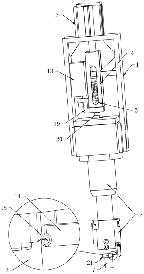
[0060] see Figure 1 to Figure 7 , The air-core coil winding jig of this embodiment includes a bracket 1, a jig head 2, a core-pulling device and a clamping device, and the air-core coil winding jig is installed on the winding machine through the bracket 1.

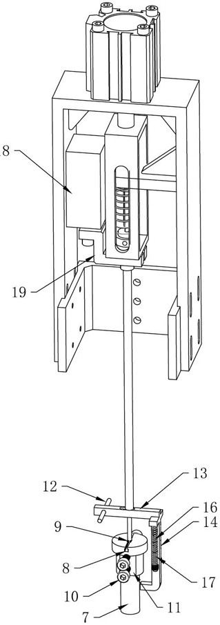
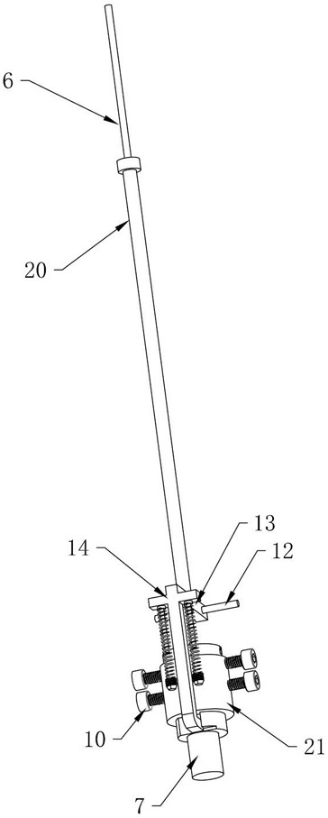
[0061] Among them, the core-pulling device includes a lifting drive device 3, a core-pulling rod 6 and a mandrel 7. The lifting drive device 3 of this embodiment can be a cylinder, an electric push rod, an electric screw, a linear motor, or other devices that can drive the core-pulling rod. 6. Lifting equipment. In this embodiment, the lifting drive device 3 is preferably a cylinder. The lifting drive device 3 is installed on the bracket 1 and drives the core-pulling rod 6 to rise or fall, and the mandrel 7 is mounted on the lower end of the core-pulling rod 6 . In order to realize fast nesting assembly, the lower end 9 of the core-pulling rod 6 is set as an I-shape, and the upper end of the mandrel 7 is provided with a ...

Embodiment 2

[0081] The main technical solution of this embodiment is basically the same as that of Embodiment 1, and the features not explained in this embodiment are explained in Embodiment 1, and will not be repeated here. In this embodiment, the end of the core sleeve 21 close to the mandrel 7 is provided with a clamping plane 11 , and the clamping plane 11 is transitionally connected with the mandrel 7 so that the enameled wire can be smoothly wound. The wire clamping part of the cross clamp 14 is provided with a wire clamping groove 15 to better clamp the enameled wire.

Embodiment 3

[0083] The main technical solutions of this embodiment are basically the same as those of Embodiment 1 or Embodiment 2, and the features not explained in this embodiment are explained in Embodiment 1 or Embodiment 2, and will not be repeated here. The present embodiment is also provided with a locking screw 10, and the clamp head 2 is provided with a screw hole, and one end of the locking screw 10 can pass through the screw hole of the clamp head 2 and connect with the core sleeve 21 so that the clamp head 2 and the core The sleeve 21 is locked, and the side where the core sleeve 21 connects with the locking screw 10 is set as a plane. The core sleeve 21 and the jig head 2 can be locked by the locking screw 10 to prevent the core sleeve 21 and the jig head 2 from rotating relative to each other and sliding up and down.


PUM


Abstract

The invention relates to a hollow coil winding clamp, a cross clamp of the hollow coil winding clamp can achieve power of wire clamping action and clamp loosening action under the action of a clamp pressing air cylinder, the action is simple, and wire clamping is rapid and efficient. The power of the wire clamping action of the cross clamp directly comes from the extension of an air cylinder, an ejector sleeve is a long-strip-shaped cylindrical object, and the arm length can be increased, so that the moment generated under the condition that the spring force is reduced is enough to open the clamp. The hollow coil winding clamp has the advantages of small resistance generated by extension of the pressing and clamping cylinder, large force of the clamp pressing on the enameled wire, good wire clamping effect and the like.

Description

technical field [0001] The invention relates to the technical field of air-core coil winding, in particular to an air-core coil winding fixture and a winding method. Background technique [0002] Hollow coils are generally wound from a single strand of enameled wire. The hollow coil winding operation is to make the enameled wire go around the mandrel of the fixture. The winding fixture of the prior art has the problem of not being able to clamp the enameled wire well, or the clamping force is too small, and the clamp cannot hold the wire. When the spool rotates, the starting thread is too short, resulting in poor coil, or even the thread and the clip are completely separated, causing the machine to run idly, reducing the output, and wasting electricity; or the clamping force is too large and the opening angle of the clip is too small. , the wire cannot be fed between the clip and the rotating shaft, resulting in failure of the wire clamping process. [0003] Therefore, in ...

Claims


Application Information

Patent Timeline
Patent Type & Authority Applications(China)
IPC IPC(8): H01F41/06H01F41/071
CPCH01F41/06H01F41/071
Inventor 佘青云汪民
Owner GUANGDONG DECE TECH LTD
Why Eureka
Try Eureka