Wind-resistant protection device for photovoltaic power station

A protection device and photovoltaic power station technology, applied in photovoltaic power generation, photovoltaic modules, photovoltaic module support structures, etc., can solve the problems of photovoltaic panel damage, smashing, photovoltaic receiving efficiency reduction, etc., and achieve the effect of protection from loss

Pending Publication Date: 2022-01-21
张文芳
View PDF0 Cites 1 Cited by
  • Summary
  • Abstract
  • Description
  • Claims
  • Application Information

AI Technical Summary

Problems solved by technology

[0005] In order to overcome the shortcomings in the prior art that photovoltaic panels are easily damaged and the receiving efficiency of photovoltaics will be reduced, the technical problem is to provide a method that can preve

Method used


Image

  • Wind-resistant protection device for photovoltaic power station
  • Wind-resistant protection device for photovoltaic power station
  • Wind-resistant protection device for photovoltaic power station

Examples


Example Embodiment

[0035] Example 1

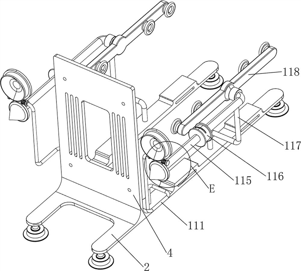
[0036] A photovoltaic power station wind protection device, such as Figure 1 to Figure 8 As shown, it includes a chassis 1, a mounting plate 2, a shock absorbing plate 3, a wind-resistant plate 4, a first linear spring 5, a first slide bar 6, a fixing mechanism 7 and a manual protection mechanism 8, and the bottom of the mounting plate 2 is left and right. The chassis 1 is equipped with both front and rear symmetry, and the wind-resistant plate 4 is provided on the top and front side of the installation plate 2. There are multiple air vents on the wind-resistant plate 4. The upper and lower sides of the wind-resistant plate 4 are symmetrically sliding. A slide bar 6, a damping plate 3 is connected between the front side of the first slide bar 6, four first linear springs 5 ​​are connected between the shock absorbing plate 3 and the wind-resistant plate 4, and the four first linear springs 5 are respectively wound on the four first sliding rods 6, the mount...

Example Embodiment

[0040] Example 2

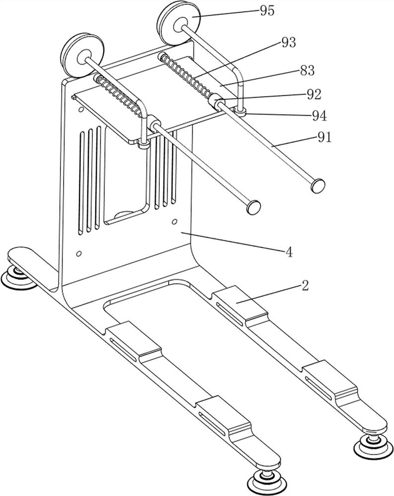
[0041] On the basis of Example 1, such as figure 1 , figure 2 , Figure 9 , Figure 10 , Figure 11 , Figure 12 , Figure 13 , Figure 14 and Figure 15 As shown, an automatic protection mechanism 9 is also included, and the automatic protection mechanism 9 includes the third slide bar 91, the third fixed column 92, the third linear spring 93, the fourth fixed column 94 and the first wind gathering disk 95, and the wind resistance A third slide bar 91 is arranged symmetrically on the rear upper side of the board 4, and the third slide bar 91 is located on the upper side of the first protective transparent plate 81, and a third fixed column 92 is arranged left and right symmetrically on the rear side of the top of the third protective transparent plate 83. , the third fixed column 92 is slidably connected with the third slide bar 91, and the third linear spring 93 is connected between the third slide bar 91 and the third fixed column 92, and the thi...


PUM


Abstract

The invention relates to a protection device, in particular to a wind-resistant protection device for a photovoltaic power station. The technical problem is to provide the wind-resistant protection device for the photovoltaic power station, which can prevent an object from being blown by wind to smash a photovoltaic panel and can ensure that the receiving efficiency of the photovoltaic panel is not reduced. According to the technical scheme, the wind-resistant protection device for the photovoltaic power station comprises chassis, a mounting plate, a damping plate, a wind-resistant plate, first sliding rods and the like. The chassis are symmetrically arranged on the two sides of the bottom of the mounting plate, the number of the chassis is four, and the wind-resistant plate is arranged on one side of the top of the mounting plate. The first sliding rods are symmetrically arranged on the upper side and the lower side of the wind resisting plate in a sliding mode, and the damping plate used for reducing the wind speed is connected between the first sliding rods. According to the invention, under the action of the damping plate and the wind-resistant plate, wind cannot be completely blown to the photovoltaic panel, so that the photovoltaic panel can be effectively protected from loss.

Description

technical field [0001] The invention relates to a protection device, in particular to a wind resistance protection device for a photovoltaic power station. Background technique [0002] Solar energy is a kind of renewable energy. People can convert solar energy into electrical energy through photovoltaic power plants. In photovoltaic power plants, photovoltaic panels are one of the most important components. Because they need to receive sunlight, photovoltaic panels are directly exposed It is in the air, and the surrounding area is generally relatively open, which is convenient for sunlight. [0003] Because the surrounding area of ​​the photovoltaic power station is relatively open, sometimes strong winds will be generated. When the wind is strong, it may cause certain damage to the photovoltaic panels, and some objects will be blown onto the photovoltaic panels, and the surface of the photovoltaic panels will be damaged. If it is smashed, most of the current protection de...

Claims


Application Information

Patent Timeline
IPC IPC(8): H02S20/30H02S40/00
CPCH02S20/30H02S40/00Y02E10/50
Inventor 张文芳
Owner 张文芳
Why Eureka
Try Eureka