Water and air discharging non-return valve

A non-return valve and non-return technology, applied in the direction of valve details, control valves, safety valves, etc., can solve problems such as endangering the ecological environment and sanitation, and achieve the effects of no loss of protection, convenient installation, and simple structure

Pending Publication Date: 2017-05-31
云南三星机械设备制造股份有限公司
View PDF13 Cites 0 Cited by
  • Summary
  • Abstract
  • Description
  • Claims
  • Application Information

AI Technical Summary

Problems solved by technology

[0002] In reservoirs, ponds, artificial lakes, sewage treatment ponds, chemical raw material storage ponds, garbage disposal sites, smelter slag and other places, lay on the original dry storage plate, pond plate, pool plate and dry ground The impermeable geomembrane (or isolation layer) is covered. After the reservoir is impounded, the water seeps into the permeable layer at the bottom of the geomembrane to replace the air in the soil pores, and the gas supports the impermeable geomembrane (or isolation layer). If there is no venting measure, the anti-seepage geomembrane (or isolation layer) will be broken. After water storage, if the water level of the reservoir drops and the seepage at the bottom of the anti-seepage geomembrane (or isolation layer) cannot be discharged quickly, the infiltration Water pressure will support the anti-seepage geomembrane (or isolation layer) so as to break or float. In addition, if the cofferdam is built at the upstream end of the laid anti-seepage geomembrane (or isolation layer) during the construction period, the enclosure After the water is blocked by the weir, the water seeps into the bottom of the anti-seepage geomembrane (or isolation layer) and supports the anti-seepage geomembrane (or isolation layer), which will break or bulge the anti-seepage geomembrane (or isolation layer), and the sewage and Toxic liquid seeps into the soil, endangering the health of the surrounding ecological environment

Method used


Image

  • Water and air discharging non-return valve
  • Water and air discharging non-return valve
  • Water and air discharging non-return valve

Examples


Embodiment Construction

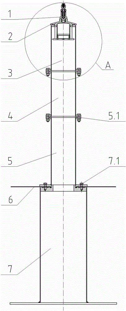
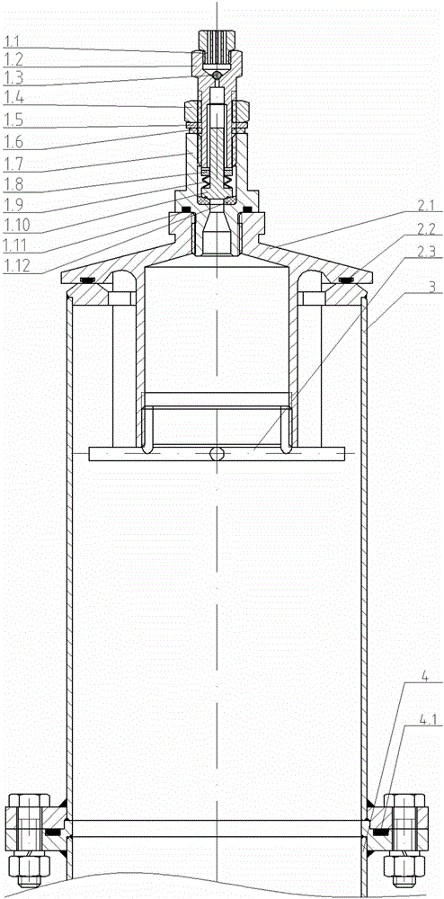
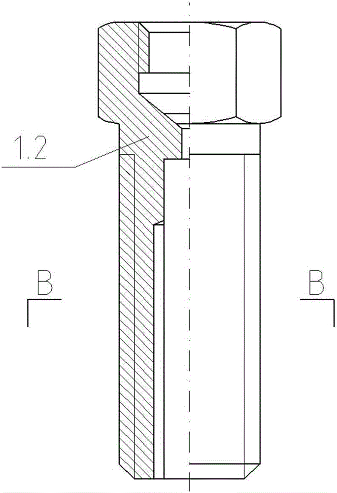
[0029] like Figure 1-19 As shown in the figure, the drain and exhaust check valve is composed of a check valve 1, a check valve 1, a check cover 2, an upper cylinder 3, a heightened cylinder 4, a middle cylinder 5, an isolation layer 6 and a lower cylinder 7. The isolation layer 6 is the anti-penetration geomembrane, the lower part of the anti-breathing and permeable valve 1 is sleeved with an O-type sealing ring I, and the lower thread of the anti-breathing and permeable valve 1 is connected with the upper end thread of the anti-water permeable cover 2, wherein the O-type sealing ring 1 is to prevent external The water penetrates into the reverse water permeable cover 2. The lower end of the reverse water permeable cover 2 is equally divided into four guide strips which are inserted into the grooves at the upper end of the upper cylinder 3 and can slide up and down with clearance fit. Ring 2.2, in which the T-shaped sealing ring 2.2 is used to prevent external water from inf...


PUM


Abstract

The invention discloses a water and air discharging non-return valve which comprises a non-return air and water permeable valve, a non-return water permeable cover, an upper cylinder, a heightening cylinder, a middle cylinder, isolating layers and a lower cylinder. The lower portion of the non-return air and water permeable valve is sleeved with O-shaped seal rings I. Four guiding bars are uniformly distributed at the lower end of the non-return water permeable cover. The guiding bars are inserted into a groove in the upper end of the upper cylinder and can slide up and down in a clearance fit mode. The lower portion of the non-return water permeable cover is lined with T-shaped seal rings. O-shaped seal rings II are mounted between the upper cylinder and the heightening cylinder. O-shaped seal rings III are mounted between the heightening cylinder and the middle cylinder. A flange at the lower end of the middle cylinder is sleeved with the isolating layer and is connected with a flange at the upper end of the lower cylinder through a bolt. O-type seal rings IV are mounted on the flange at the upper end of the lower cylinder. By mean of the water and air discharging non-return valve, water and air at the bottom of a laid permeation-resisting geomembrane can be discharged in time to protect the bottom of the laid isolating layer, the damage of water and air to the isolating layer is prevented, and the situation that sewage and harmful liquid permeate into soil to pollute the soil and groundwater, and endanger surrounding ecological environment health is effectively prevented.

Description

technical field [0001] The invention relates to water conservancy and hydropower reservoirs, ponds, artificial lakes, sewage treatment pools, chemical raw material stacking pools, garbage disposal sites, smelting plant slag yards and other places, which are used to prevent sewage and toxic liquids from penetrating into the soil. It is a device for exhausting and preventing damage to the laying of anti-permeability geomembrane or damage to the isolation layer, specifically a drainage and exhaust check valve. Background technique [0002] In reservoirs, ponds, artificial lakes, sewage treatment ponds, chemical raw material storage ponds, garbage disposal sites, smelter slag and other places, lay on the original dry storage plate, pond plate, pool plate and dry ground The impermeable geomembrane (or isolation layer) is covered. After the reservoir is impounded, the water seeps into the permeable layer at the bottom of the geomembrane to replace the air in the soil pores, and th...

Claims


Application Information

Patent Timeline
Patent Type & Authority Applications(China)
IPC IPC(8): F16K17/04F16K17/06F16K15/04F16K27/02
CPCF16K15/04F16K17/048F16K17/06F16K27/0209F16K27/0245F16K27/0254
Inventor 王文秀周世平
Owner 云南三星机械设备制造股份有限公司
Why Eureka
Try Eureka