Deposit removing device and deposit removing method

A technology for attachments and exhaust ports, which is applied in the field of attachment removal devices, and can solve problems such as increased resistance of exhaust pipes, increased possibility, and large pressure fluctuations

Pending Publication Date: 2022-01-21
SUMCO CORP
View PDF8 Cites 0 Cited by
  • Summary
  • Abstract
  • Description
  • Claims
  • Application Information

AI Technical Summary

Problems solved by technology

[0010] (2) The pipe resistance of the exhaust pipe whose inner diameter becomes smaller due to the deposits increases, so it becomes difficult to control the pressure in the chamber and the pressure in the chamber tends to fluctuate greatly
As a result, the possibility of occurrence of the problems shown in (1) to (3) above increases.

Method used


Image

  • Deposit removing device and deposit removing method
  • Deposit removing device and deposit removing method
  • Deposit removing device and deposit removing method

Examples


Embodiment approach 1

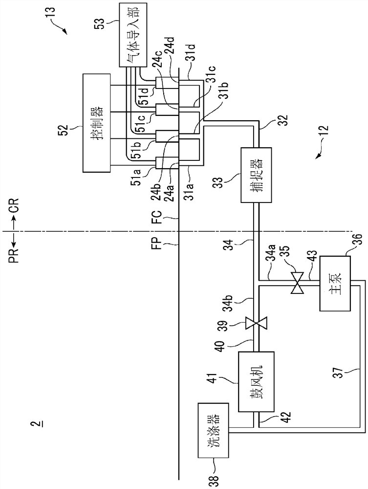
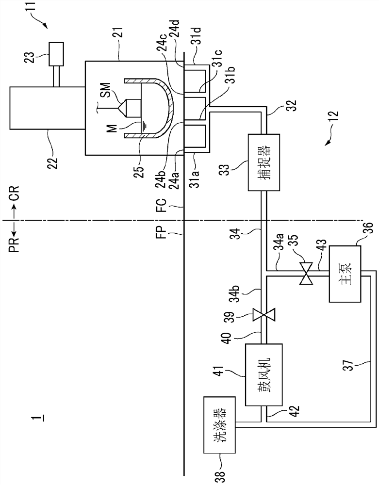
[0042] figure 1 It is a conceptual diagram showing an example of the structure of the deposit removal device 2 according to Embodiment 1 of the present invention, figure 2 It is a front view showing an example of the structure of the exhaust port opening and closing mechanism 51 a constituting the deposit removing device 2 . and, image 3 It is a conceptual diagram showing an example of the structure of the semiconductor crystal manufacturing apparatus 1 to which the deposit removal apparatus 2 is applied.

[0043] First, refer to image 3 An example of the structure of the semiconductor crystal manufacturing apparatus 1 will be described. The semiconductor crystal manufacturing apparatus 1 manufactures single crystal silicon by the CZ method. The semiconductor crystal manufacturing apparatus 1 includes a semiconductor crystal manufacturing unit 11 and a gas exhaust unit 12 .

[0044] The semiconductor crystal manufacturing unit 11 is installed on the floor FC of the cl...

Embodiment approach 2

[0092] In the first removal step of Embodiment 1 above, as Figure 7 As shown, an example in which short-term opening is performed from the first on-off valve to the fourth on-off valve after short-term opening from the first on-off valve to the fourth on-off valve is shown, but the present invention is not limited thereto. For example, short-term opening of the second on-off valve and subsequent opening of the second on-off valve may be performed multiple times after short-term opening of the first on-off valve. In addition, the order of opening and closing of the first on-off valve to the fourth on-off valve is not particularly limited.

Embodiment approach 3

[0094] In the first removal step of the above-mentioned Embodiments 1 and 2, as Figure 7 As shown, an example is shown in which only one on-off valve is opened for a short period of time, and then only the other on-off valve is opened for a short period of time after the elapse of the period T1, but it is not limited thereto. Short-term opening of a plurality of on-off valves may be simultaneously performed without passing the period T1. In this way, working time can be shortened.


PUM


Abstract

This deposit removing device disclosed herein removes deposits attached to an exhaust pipe for discharging gas from a chamber for manufacturing semiconductor crystals. The present invention is provided with an exhaust port opening / closing means (51a) having: a valve body (69) for opening / closing an exhaust port (24a) communicating with an exhaust pipe; a sealing cover (66) and a fixed stand (65) which accommodate the valve body (69), can introduce an inert gas, and can separate the exhaust port (24a) from the outside; a cylinder (67) for driving the valve body (69); and a cylinder (73) for driving the sealing cover (66) and the fixed stand (65). The exhaust port (24a) is opened / closed by driving the valve body (69) by means of the cylinder (67), and atmospheric air is introduced into the sealing cover (66) by driving the sealing cover (66) or the fixed stand (65) by means of the cylinder (73).

Description

technical field [0001] The present invention relates to a deposit removal device and a deposit removal method for removing deposits attached to an exhaust pipe that discharges gas from a chamber for manufacturing semiconductor crystals. Background technique [0002] In semiconductor crystal manufacturing equipment, semiconductor crystals are manufactured using a single crystal growth method such as the Czochralski method (hereinafter referred to as "CZ method") or the floating zone method (hereinafter referred to as "FZ method") . [0003] In the CZ method, for example, single-crystal silicon is extracted from a silicon melt melted in a quartz crucible installed in a chamber. During this manufacturing process, oxygen (O 2 ) from silicon dioxide (SiO 2 ) as the composition of the quartz crucible dissolves and reacts with the silicon melt to form silicon oxide (SiOx) or silicon dioxide (SiO 2 ). The silicon oxide (SiOx) or the silicon dioxide (SiO 2 ) evaporate from the ...

Claims


Application Information

Patent Timeline
Patent Type & Authority Applications(China)
IPC IPC(8): C30B31/16B08B5/04B08B13/00
CPCC30B31/16B08B5/04B08B13/00C30B29/06C30B15/00B08B9/027C30B35/00B08B9/035B08B2209/032C30B13/00
Inventor 小川福生四井拓也前川浩一
Owner SUMCO CORP
Why Eureka
Try Eureka