Clinical energy-saving medical gauze disinfection device and method

A disinfection device and energy-saving technology, which is applied in disinfection, water supply devices, sanitary equipment for toilets, etc., can solve the problems of slow gauze opening efficiency, lack of continuity and real-time performance, and easy damage to the device, so as to meet the needs of any time The effect of taking

Active Publication Date: 2022-01-25
THE AFFILIATED HOSPITAL OF QINGDAO UNIV
View PDF7 Cites 0 Cited by
  • Summary
  • Abstract
  • Description
  • Claims
  • Application Information

AI Technical Summary

Problems solved by technology

[0003]At this stage, large rolls of gauze are generally sterilized by ultraviolet lamp irradiation, such as reference document 201811085311.7 A gauze disinfection device provides a device that can It is reciprocatingly opened in an S shape, which is convenient for the irradiation of the ultraviolet lamp tube, so as to realize the rapid disinfection of gauze. After the irradiation and disinfection are completed, it is reset and wound. This method of gauze disinfection has the following problems. First, the rolled gauze is placed in the disinfection box The internal opening needs to be reset and rewound before use after being sterilized, which does not have the continuity and real-time performance of use. Second, there are too many driving parts for the opening of the gauze, the efficiency of the opening of the gauze is slow, and the complex coordination of various parts is prone to jamming. The device is easily damaged. Third, the number of ultraviolet lamps in the disinfection box is large and the utilization efficiency is low, which does not meet the energy-saving requirements

Method used


Image

  • Clinical energy-saving medical gauze disinfection device and method
  • Clinical energy-saving medical gauze disinfection device and method
  • Clinical energy-saving medical gauze disinfection device and method

Examples


Embodiment Construction

[0021] The specific implementation manners of the present invention will be described in further detail below in conjunction with the accompanying drawings.

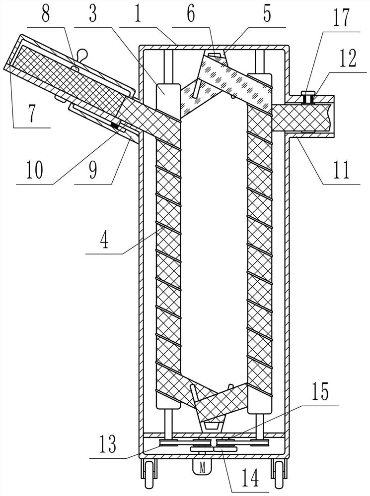
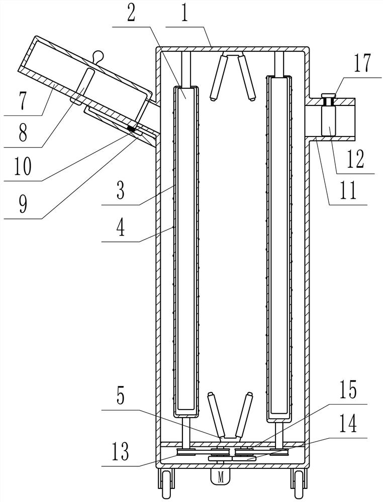
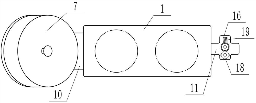
[0022] Depend on Figure 1 to Figure 3 It can be seen that the present invention includes a box body 1, and the box body 1 is provided with two vertical and left and right ultraviolet lamp tubes 2 installed at intervals. The suit is equipped with a glass cover 3, the glass cover 3 is a round tube with a closed lower end, the two glass covers 3 rotate in reverse synchronously, each glass cover 3 is provided with a thread guide protrusion 4, and the upper and lower ends of the box body 1 are respectively fixed Two left-right symmetrical guide rods 5 are installed, and the free ends of the guide rods 5 are inclined to the direction of the corresponding side glass cover 3, and the closed-loop soft belt 6 made of transparent material is wound on the two glass covers 3, and the closed-loop soft belt 6 starts from the left side...


PUM


Abstract

The invention relates to a clinical energy-saving medical gauze disinfection device and method. The clinical energy-saving medical gauze disinfection device comprises a box body, two vertical ultraviolet lamp tubes are arranged in the box body in a left-right spaced mode, the outer side of each ultraviolet lamp tube is sleeved with a glass cover, the two glass covers synchronously and reversely rotate, each glass cover is provided with a threaded guide protrusion, the upper end and the lower end of the box body are each fixedly provided with two guide rods which are symmetrical left and right, the two glass covers are wound with closed-loop soft belts made of transparent materials, the closed-loop soft belts are driven to rotate when the two glass covers synchronously and reversely rotate, a cavity with the axis upper end inclining rightwards is formed in the upper end of the left side of the box body, a through groove is formed in the side, close to the box body, of the cavity, a pin shaft is coaxially and rotationally installed in the cavity, the gauze roll is installed on the pin shaft of the cavity, a feeding pipe corresponding to the through groove is arranged on the left side of the box body, a discharging pipe is arranged on the right side of the box body, and two driving rollers capable of synchronously and reversely driving are arranged on the discharging pipe.

Description

technical field [0001] The invention relates to the field of medical equipment, in particular to a clinical energy-saving medical gauze disinfection device and method. Background technique [0002] In the emergency department, dressing room, orthopedic clinic and other departments, a large amount of gauze is consumed every day. At this stage, gauze is divided into individually packaged small rolls of sterile gauze and large rolls of gauze. Individually packaged small rolls of sterile gauze are passed through sterile bags After opening the bag, it can be directly in contact with the affected area, but this kind of gauze has certain limitations in use due to its fixed length, and there is more or less waste. Large rolls of gauze are sterilized before leaving the factory. Since it cannot be used up at one time, real-time disinfection is required during use, but this type of gauze can be cut to length according to needs to avoid waste, and is generally used for fixing and wrappi...

Claims


Application Information

Patent Timeline
IPC IPC(8): A61L2/10A61L2/26
CPCA61L2/10A61L2/26A61L2202/26
Inventor 王桂莲
Owner THE AFFILIATED HOSPITAL OF QINGDAO UNIV
Why Eureka
Try Eureka