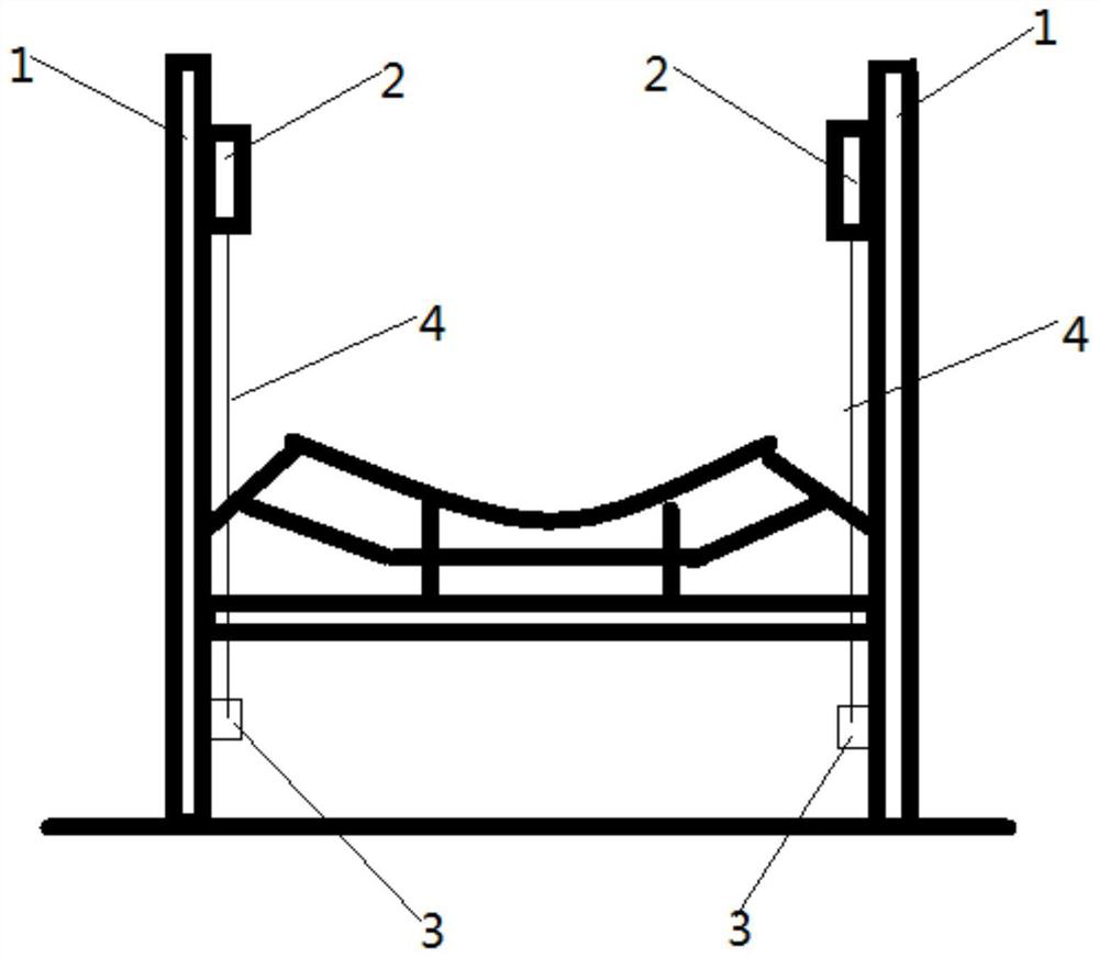
W-shaped bidirectional pull rope switch device for coal conveyer belt

A technology of pull rope switch and belt, which is applied in the direction of conveyor control device, electric switch, transportation and packaging, etc. It can solve the problem that the pull rope switch affects the life and accuracy of equipment, increases the time of emergency shutdown of personnel, and the degree of damage of the pull rope switch Large and other problems, to achieve high-speed and effective emergency shutdown, improve construction safety, and simple structure

Pending Publication Date: 2022-01-25
SHANDONG RIZHAO POWER GENERATION CO LTD
View PDF10 Cites 0 Cited by
  • Summary
  • Abstract
  • Description
  • Claims
  • Application Information

AI Technical Summary

Problems solved by technology

[0003] The installation position of the existing two-way pull rope switch is relatively low. When the coal conveyor belt trestle is cleaned by hydraulic force, it is very easy to cause water in the pull rope switch to affect the life and accuracy of the equipment; Low, and the height of the coal conveying belt is generally about 140cm. In an accident, if the person is above the working surface of the belt, the belt suddenly opens, and the above person cannot touch the pull rope switch at the lower part to realize the self-rescue function; secondly, the existing pull rope switch It can only realize the function of emergency shutdown, without any other auxiliary functions. Finally, because the installation position of the pull rope switch and the pull wire is low, when an emergency shutdown is required, the personnel need to bend down to reach the pull rope. The time for emergency shutdown of personnel; and when employees are anxious, they will take violent methods to step on the pull rope switch with their feet. Not only the success rate of stepping on it is low, but also the degree of damage to the pull rope switch is great.

Method used


Image

  • W-shaped bidirectional pull rope switch device for coal conveyer belt
  • W-shaped bidirectional pull rope switch device for coal conveyer belt

Examples


Embodiment Construction

[0021] The present invention will be further described in detail below in conjunction with specific embodiments, which are explanations of the present invention rather than limitations.

[0022] In order to enable those skilled in the art to better understand the solutions of the present invention, the following will clearly and completely describe the technical solutions in the embodiments of the present invention in conjunction with the drawings in the embodiments of the present invention. Obviously, the described embodiments are only It is an embodiment of a part of the present invention, but not all embodiments. Based on the embodiments of the present invention, all other embodiments obtained by persons of ordinary skill in the art without making creative efforts shall fall within the protection scope of the present invention.

[0023] It should be noted that the terms "first" and "second" in the description and claims of the present invention and the above drawings are us...


PUM


Abstract

The invention provides a W-shaped bidirectional pull rope switch device for a coal conveyer belt. A pull wire is connected between a bidirectional pull rope switch and a fixing pull ring which are adjacently arranged, and used for pulling in case of emergency shutdown, and therefore the coal conveyer belt can be stopped; through the bidirectional pull rope switch arranged on the top of a fixing side plate, the probability that water enters the pull rope switch during hydraulic cleaning of a coal conveyer trestle can be reduced, and the service life of the bidirectional pull rope switch is further prolonged; meanwhile, if the coal conveyer belt is deviated greatly, the pull wire on the side of the coal conveyer belt can be triggered, and emergency shutdown is achieved; the service life of the coal belt conveyor is prolonged; when emergency shutdown is needed, an operator does not need to bend down, the pull rope switch can be touched at all horizontal heights,and the emergency shutdown function is achieved; the emergency shutdown efficiency and the construction safety are improved; finally, if a constructor is above the coal conveying belt, the pull wire can be further rapidly pulled, and therefore the emergency shutdown is achieved; the structure is simple, and meanwhile the emergency shutdown of the coal belt conveyor can be effectively achieved at high speed; and the safety is high.

Description

technical field [0001] The invention belongs to the field of electrical equipment, and in particular relates to a W-shaped coal conveying belt bidirectional pull rope switch device. Background technique [0002] The two-way pull rope switch is an essential protection device for the belt conveyor at present. It is used to pull the wire rope when the belt conveyor needs to be shut down due to an emergency or maintenance. [0003] The installation position of the existing two-way pull rope switch is relatively low. When the coal conveyor belt trestle is cleaned by hydraulic force, it is very easy to cause water in the pull rope switch to affect the life and accuracy of the equipment; Low, and the height of the coal conveying belt is generally about 140cm. In an accident, if the person is above the working surface of the belt, the belt suddenly opens, and the above person cannot touch the pull rope switch at the lower part to realize the self-rescue function; secondly, the exist...

Claims


Application Information

Patent Timeline
Patent Type & Authority Applications(China)
IPC IPC(8): B65G43/00B65G43/02H01H17/00
CPCB65G43/00B65G43/02H01H17/00
Inventor 周小宝
Owner SHANDONG RIZHAO POWER GENERATION CO LTD
Why Eureka
Try Eureka