Multifunctional cable pay-off device applied to municipal power construction

A technology of electric power construction and pay-off device, which is applied in the direction of cable installation device, cable installation, cutting/split cable equipment, etc., and can solve problems such as low stability and shaking of the reel

Active Publication Date: 2022-01-25
STATE GRID CORP OF CHINA +1
View PDF6 Cites 1 Cited by
  • Summary
  • Abstract
  • Description
  • Claims
  • Application Information

AI Technical Summary

Problems solved by technology

[0003] However, there are two types of traditional pay-off devices, one is to support the center hole of the reel, which is suitable for small reels; the other is Use supporting rollers to support the outer circle of the reel, which is suitable for large reels; this kind of pay-off device has the following

Method used


Image

  • Multifunctional cable pay-off device applied to municipal power construction
  • Multifunctional cable pay-off device applied to municipal power construction
  • Multifunctional cable pay-off device applied to municipal power construction

Examples


Embodiment 1

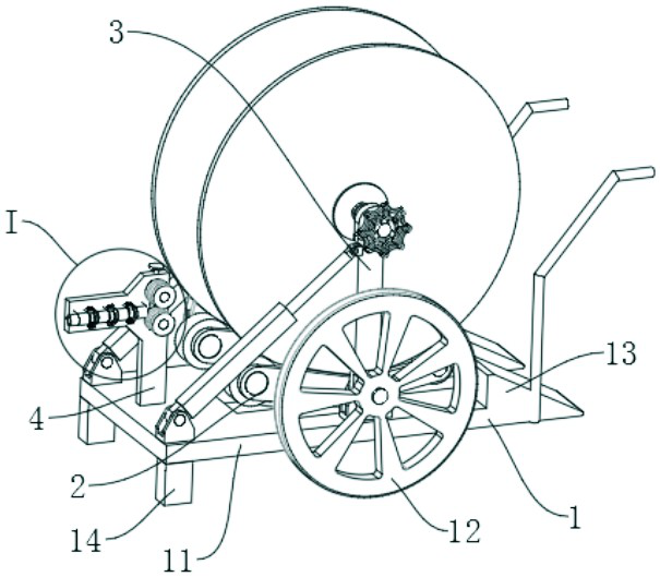
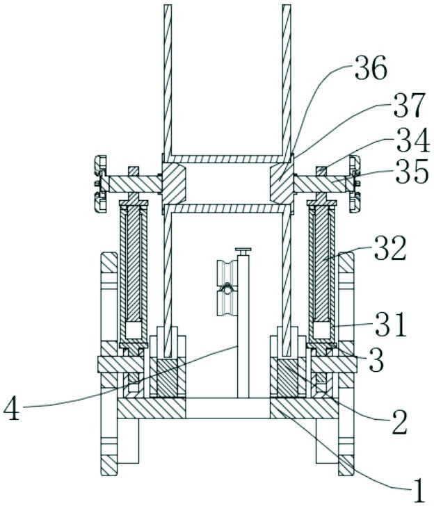
[0034] Embodiment one, such as Figure 1-7As shown, a multifunctional cable pay-off device applied to municipal electric power construction includes a mobile trolley 1, a supporting wheel mechanism 2, and an auxiliary mechanism 3. The middle part of the upper surface of the mobile trolley 1 is provided with a coil for supporting the wire to be unwound. The supporting wheel mechanism 2 of the wire reel, the upper plate surface of the mobile cart 1 located on both sides of the supporting wheel mechanism 2 is equipped with a wire reel to be placed on the supporting wheel mechanism 2, and the auxiliary supporting wheel mechanism 2 is stable. Auxiliary mechanism 3 of the wire reel for unwinding; auxiliary mechanism 3 includes sleeve pipe 31, inner rod 32, electric telescopic rod 33, mounting block 34, first lead screw 35, support shaft 36, annular baffle plate 37, sleeve pipe 31 The lower end is hinged with the upper surface of the mobile trolley 1, the inner cavity of the casing 3...

Embodiment 2

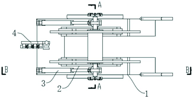
[0036] Embodiment two, on the basis of embodiment one, such as Figure 1-5 As shown, the supporting wheel mechanism 2 includes a fixed seat 21, a mounting seat 22, a first supporting wheel 23, a second supporting wheel 24, and a first wedge block 26. The mounting seat 22 is a V-shaped structure, and the tip is installed on the mobile cart 1. The fixed seat 21 on the upper plate surface is hinged, and the ends on both sides of the opening of the mounting seat 22 are respectively rotated and connected to the first supporting wheel 23 and the second supporting wheel 24 for supporting the surface of the reel to be unwound, and the mobile trolley 1 The upper plate surface is provided with the first wedge-shaped block 26 corresponding to the opening side of the mounting seat 22, and the mounting seat 22 can also be a T-shaped structure or other structures, as long as it can ensure that the first support roller 23 and the second support roller 24 are compatible with the The surface o...

Embodiment 3

[0039] Embodiment three, on the basis of embodiment one, such as figure 1 As shown, the mobile trolley 1 includes a base plate 11, wheels 12, and support legs 14. Push handles are provided on both sides of one end of the base plate 11, wheels 12 are provided at the middle position on both sides of the base plate 11, and a support for supporting the base plate 11 is provided at the other end of the base plate 11. Support leg 14, and the height of support leg 14 is lower than wheel 12 and is positioned at the height of base plate 11 lower part, arranges like this when support leg 14 touches the ground, base plate 11 is in the state of inclination, and rear end is inclined downward, can pass support leg like this 14 is on the ground so that the mobile trolley 1 will not move autonomously. Therefore, when unwinding, there is no need for a staff to hold the mobile trolley 1. Since the wheels are located on both sides of the base plate 11, and the wheel axles of the wheels are locate...


PUM

PropertyMeasurementUnit
Diameteraaaaaaaaaa

Abstract

The invention relates to the technical field of cable pay-off, in particular to a multifunctional cable pay-off device applied to municipal electric power construction. The device comprises a movable plate trailer, a riding wheel mechanism and auxiliary mechanisms, wherein the riding wheel mechanism for supporting a winding roll to be paid off is arranged in the middle of the upper plate surface of the movable plate trailer; and the upper plate faces, located on the two sides of the riding wheel mechanism, of the movable plate trailer are each provided with an auxiliary mechanism used for placing the winding roll to be paid off on the riding wheel mechanism and assisting the riding wheel mechanism to stabilize the winding roll to be paid off. Through the arrangement of the auxiliary mechanisms, the function of automatically placing the winding roll on the riding wheel mechanism is achieved, and the function of preventing the winding roll from swinging left and right in the pay-off process is achieved; and due to the arrangement of the riding wheel mechanism, the winding roll can be conveniently moved to the riding wheel mechanism, and a second riding wheel is prevented from being impacted by the winding roll.

Description

technical field [0001] The invention relates to the field of cable pay-off technology, in particular to a multifunctional cable pay-off device applied to municipal power construction. Background technique [0002] The so-called electric power engineering refers to projects related to the production, transmission and distribution of electric energy. In a broad sense, it also includes projects that use electricity as power and energy in various fields. In electric power engineering, cable laying is a very critical work. Coiled on the reel, the reel needs to be installed on the pay-off frame to pay off the wire. [0003] However, there are two types of traditional pay-off devices, one is to support the center hole of the reel, which is suitable for small reels; the other is to use supporting wheels to support the outer circle of reels, which is suitable for large There are the following defects in this kind of pay-off device; 1. The upper and lower positions of the supporting ...

Claims


Application Information

Patent Timeline
IPC IPC(8): B65H49/20B65H49/34H02G1/00H02G1/12
CPCB65H49/20B65H49/34H02G1/005H02G1/1265Y02W30/82
Inventor 孟凡斌曹翀王正钊郑罡王磊
Owner STATE GRID CORP OF CHINA
Why Eureka
Try Eureka