Adjustable supporting device for steel bar truss floor support plate

A steel truss and support device technology, applied in the field of adjustable support devices, can solve the problem that the support frame cannot adapt to steel trusses of different sizes and lengths

Pending Publication Date: 2022-01-28
江西建邦科技有限公司
View PDF0 Cites 0 Cited by
  • Summary
  • Abstract
  • Description
  • Claims
  • Application Information

AI Technical Summary

Problems solved by technology

[0005] In order to overcome the shortcomings of the existing support frame that cannot adapt to steel trusses of different sizes and lengths, the technical problem to be solved is

Method used


Image

  • Adjustable supporting device for steel bar truss floor support plate
  • Adjustable supporting device for steel bar truss floor support plate
  • Adjustable supporting device for steel bar truss floor support plate

Examples


Embodiment 1

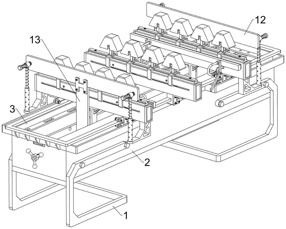
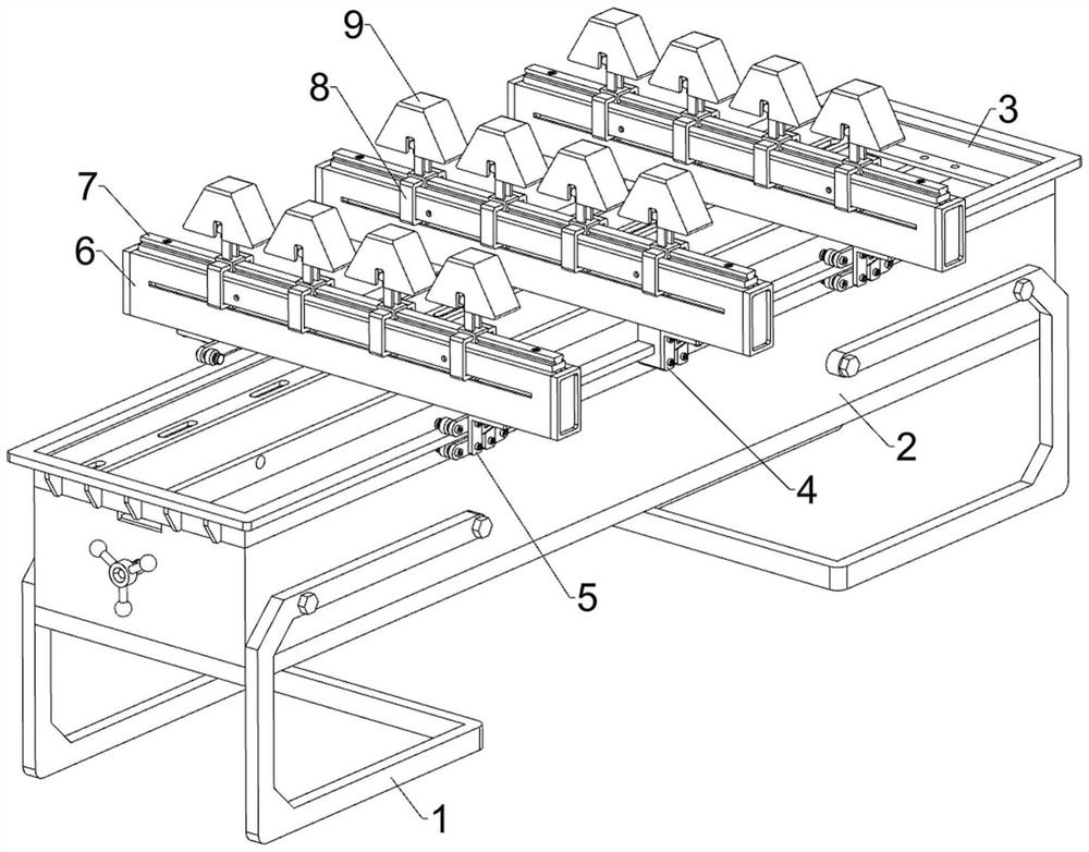
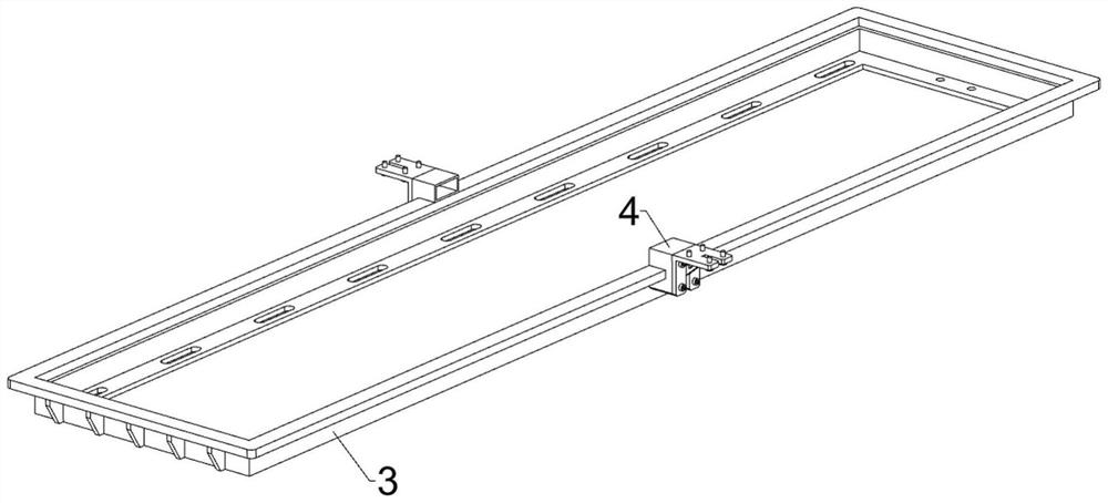
[0037] An adjustable support device for reinforced truss floor decks, see Figure 1-9As shown, it includes a support frame 1, a housing 2, a guide frame 3, a fixed frame 4, a moving frame 5, a protective case 6, a slide rail 7, a sliding plate 8, a placement block 9, an adjustment assembly 10 and a push assembly 11, left and right The upper part of the two support frames 1 is fixed with the shell 2 by bolts, the top of the shell 2 is welded with the guide frame 3, the middle part of the guide frame 3 is symmetrically fixed with the fixed frame 4 by screws, and the left and right sides of the guide frame 3 slide There are two mobile frames 5, the mobile frames 5 are arranged symmetrically front and back, the tops of the two mobile frames 5 on the same side are connected with a protective shell 6 by bolts, and the tops of the two fixed frames 4 at the front and rear are fixed by bolts. Connected with the same protective case 6, the top of the protective case 6 is welded with a s...

Embodiment 2

[0044] On the basis of embodiment 1, see figure 1 , Image 6 , Figure 10 and Figure 11 As shown, a flushing assembly 12 is also included, and the flushing assembly 12 can push the steel bar truss flat. The flushing assembly 12 includes a bracket 121, a guide cylinder 122, a sliding rod 123, a second elastic member 124, a sliding rod 125, The third elastic member 126 and the pressure plate 127, the bottom of the protective shell 6 on the left and right sides are all welded with a support 121 symmetrically front and back, the bottom of the support 121 is welded with a guide cylinder 122, and the guide cylinder 122 is provided with a sliding rod 123 in a sliding manner. A second elastic member 124 is wound around the sliding rod 123 and the adjacent guide cylinder 122. The second elastic member 124 is a compression spring. The upper part of the sliding rod 123 is slidingly provided with a sliding rod 125. The third elastic member 126 is wound around the sliding bars 123, and...


PUM


Abstract

The invention relates to an adjustable supporting device, in particular to an adjustable supporting device for a steel bar truss floor support plate. The adjustable supporting device for the steel bar truss floor support plate can adapt to steel bar trusses of different sizes and lengths and is more convenient for people to use. The adjustable supporting device for the steel bar truss floor support plate comprises supporting frames, a shell, a guide frame, a fixing frame and the like. The shell is arranged between the upper portions of the left and right supporting frames, the guide frame is arranged on the top of the shell, and fixing frames are symmetrically arranged in the middle of the guide frame front and back. A worker places the steel bar trusses between the two adjacent placing blocks, multiple positions of the steel bar trusses are supported through the three rows of placing blocks, and meanwhile, due to the fact that the distance between the placing blocks is adjustable, the steel bar trusses of different sizes can be placed on the device.

Description

technical field [0001] The invention relates to an adjustable support device, in particular to an adjustable support device used for steel truss floor decks. Background technique [0002] The steel truss is a truss composed of multiple steel bars through spot welding, most of which are triangular structures, while the steel truss floor deck is a composite load-bearing plate connected to the bottom through the steel truss. When bearing the slab, it is necessary to support the steel truss so that the staff can connect the bottom with the steel truss. [0003] At present, when the steel truss floor deck is assembled and produced, the steel truss is generally supported by a support frame. This support frame is generally composed of a base, a bracket and a placement plate. Three brackets are evenly spaced on the base. There are placement boards on the top of the brackets, and there are three placement slots equidistantly on the placement boards. When assembling the steel truss f...

Claims


Application Information

Patent Timeline
IPC IPC(8): B25H1/00B25H1/08
CPCB25H1/00B25H1/08
Inventor 罗红徐欠牛
Owner 江西建邦科技有限公司
Why Eureka
Try Eureka