Pipe traction device and traction method

A pulling device and pipe technology, applied in the field of pipe pulling devices, can solve the problems of difficult operation, time-consuming and laborious occupation of space, etc., and achieve the effect of reducing length and lengthening length.

Pending Publication Date: 2022-01-28
CHONGQING WEIXING NEW BUILDING MATERIALS
View PDF0 Cites 0 Cited by
  • Summary
  • Abstract
  • Description
  • Claims
  • Application Information

AI Technical Summary

Problems solved by technology

[0004] The present invention intends to provide a pipe traction device to solve the problems of difficult operation, time-consuming and labor-intensive operation and large space occupation of pipe traction in the prior art

Method used


Image

  • Pipe traction device and traction method
  • Pipe traction device and traction method
  • Pipe traction device and traction method

Examples


Embodiment

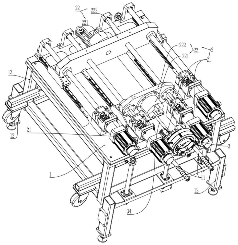
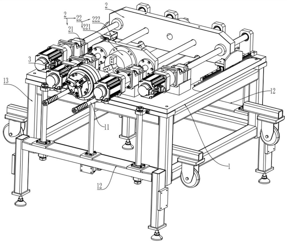
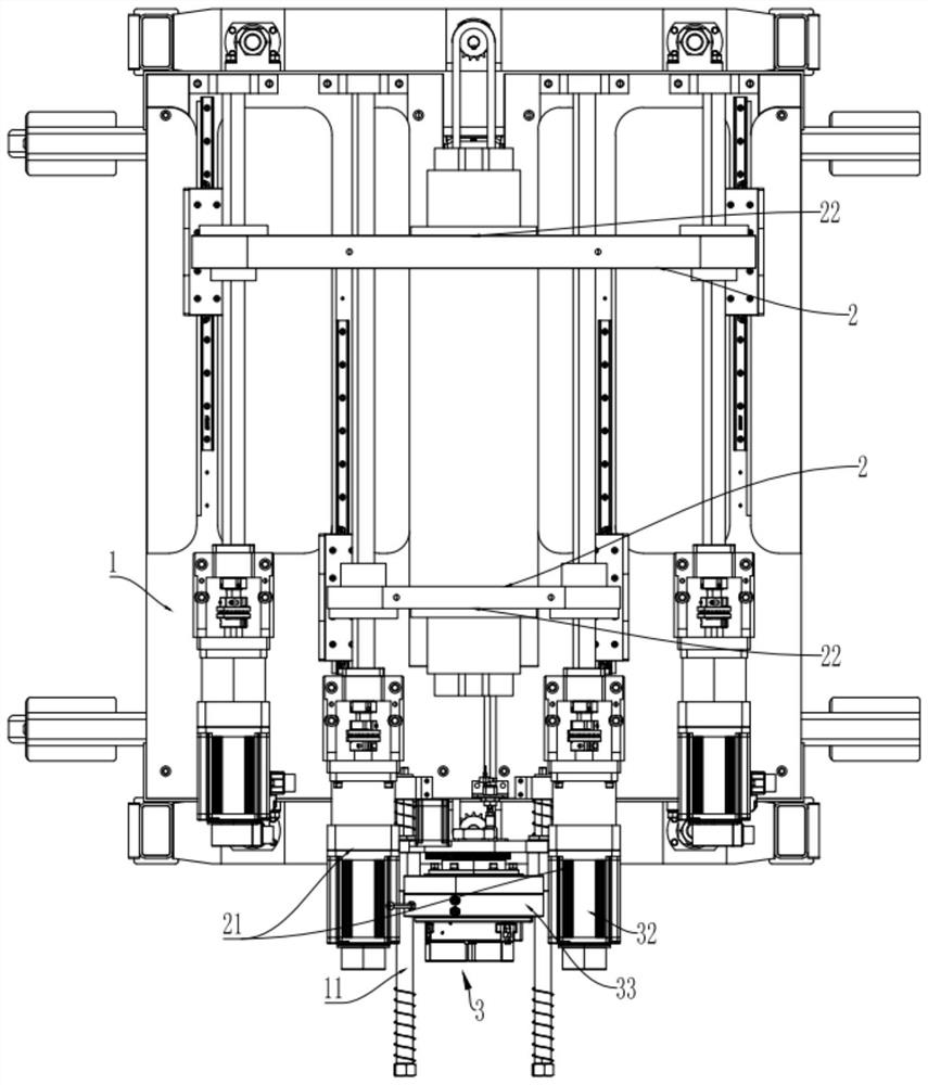
[0037] The embodiment is basically as attached Figure 1 to Figure 9 As shown, a pipe pulling device includes a frame 1 and a pulling mechanism on the frame 1, and an elastic mechanism 3. The pulling mechanism includes at least two pulling assemblies 2, and each pulling assembly 2 includes a driver 21 and is used for Clamp or loosen the clamp 22 of the traction tube, the driver 21 is used to drive the clamp 22 to move axially along the pipe, different drawing components 2 alternately clamp the traction tube to drive the traction tube to move at a constant speed; the clamp 22 includes Chuck 221 and pull plate 222, the chuck 221 is fixedly connected to the pull plate 222, the chuck 221 is used to clamp or loosen the traction pipe, the pull plate 222 is slidably connected to the frame 1 along the pipe axial direction, and the driver 21 drives The drawing plate 222 moves axially; in this embodiment, there are two drawing assemblies 2 , the driver 21 adopts a ball screw structure, an...


PUM

PropertyMeasurementUnit
lengthaaaaaaaaaa

Abstract

The invention relates to the technical field of pipe production, and particularly discloses a pipe traction device and a traction method. The pipe traction device comprises a rack and a traction mechanism on the rack, wherein the traction mechanism comprises at least two drawing assemblies, each drawing assembly comprises a driver and a clamping device used for clamping or loosening a traction pipe, the driver is used for driving the clamping device to move in the axial direction of the pipe, the different drawing assemblies alternately clamp the traction pipe so as to drive the traction pipe to move at a constant speed, the traction pipe comprises a plurality of pipe sections, and the adjacent pipe sections can be detachably connected. According to the invention, the traction device is used for conducting traction and drawing on the pipe so as to solve the problems that in the prior art, pipe traction is large in operation difficulty, time-consuming, labor-consuming and large in occupied space.

Description

technical field [0001] The invention relates to the technical field of pipe production, in particular to a pipe traction device and a traction method. Background technique [0002] In the production of pipes in the prior art, after the pipes are first produced from the forming equipment, due to the high temperature of the pipes, the pipes need to be cooled by a cooler. After the pipes are cooled, a cutter is needed to cut the continuously produced pipes into pieces part. After the pipe has just been produced from the forming equipment, the pipe itself cannot be automatically and accurately moved to the cooler for cooling due to the high temperature of the pipe. The soft pipe is welded on the traction tube, and the traction tube drives the pipe to be drawn, so that the pipe can enter the cooler and reach the cutter smoothly. [0003] Before the drawing pipe is pulled from the forming equipment, the drawing pipe itself needs to enter from the cutter and pass through the cool...

Claims


Application Information

Patent Timeline
Patent Type & Authority Applications(China)
IPC IPC(8): B29C48/355B29C48/09B29L23/00
CPCB29C48/355B29C48/09B29L2023/22
Inventor 赵银鲍哲松沈启掌樊进
Owner CHONGQING WEIXING NEW BUILDING MATERIALS
Why Eureka
Try Eureka