Gas-insulated switch

a technology of gas-insulated switches and switches, which is applied in the direction of switch power arrangements, high-tension/heavy-dress switches, and switches with metal casings. it can solve the problems of increasing the space needed for a power station and substation, the disadvantage of poor energy efficiency, and the number of outside dimensions and operating devices

Inactive Publication Date: 2003-01-23
HITACHI LTD
View PDF0 Cites 10 Cited by
  • Summary
  • Abstract
  • Description
  • Claims
  • Application Information

AI Technical Summary

Benefits of technology

[0009] An object of the present invention is to provide a gas-insulated switch wherein the energy needed to cause the moving parts to make accelerated motion and uniform motion can be lowered.
[0010] Another object of the present invention is to provide a gas-insulated switch wherein the specification requirement of a component such as a spring, pneumatic cylinder, or hydraulic cylinder, serving as the energy source of the operating device itself, used in the gas-insulated switch can be lowered.
[0011] A further object of the present invention is to provide a gas-insulated switch wherein the size of the operating device itself for driving the gas-insulated switch and the overall size of the gas-insulated switch can be reduced.
[0012] A further object of the present invention is to provide a gas-insulated switch wherein the necessary shock absorbers can be constructed into a single unit and a further reduce the size of the operating device can be attained.
[0013] A further object of the present invention is to provide a gas-insulated switch wherein the offering a gas-insulated switch that sufficiently meets the social needs such as effective utilization of the space of a power station or substation and improvement of the economy can be realized.
[0014] To solve the above-mentioned problems, the gas-insulated switch according to the present invention is equipped with a shock absorber for absorbing the shock on the fixed and moving contacts in the closing and breaking operations of the operating device, the shock absorber is installed in the breaking operation section of the operating device, and the shock is absorbed by this shock absorber in both closing and breaking operations.

Problems solved by technology

Because of this, all energy of the drive source of the operating device is not converted into the accelerated motion and uniform motion of the moving contact, hence resulting in a disadvantage of poor energy efficiency.
When the switch shown in the prior example 2 is employed, the energy efficiency improves but a shock absorber needs to be provided individually for a closing operation and for a breaking operation, still resulting in a disadvantage that the outside dimension and the number of parts of the operating device increase.
For the above reasons, when an operating device utilizing a shock absorber of the prior art is employed for a gas-insulated switch, there arises a problem that the space needed for a power station and substation increases because the component size increases and that a social need such as improvement of the economy cannot be met because the energy loss of the drive source of the operating device is high.

Method used


Image

  • Gas-insulated switch
  • Gas-insulated switch
  • Gas-insulated switch

Examples


Embodiment Construction

[0024] A preferred embodiment of the gas-insulated switch according to the present invention is explained hereunder, using figures.

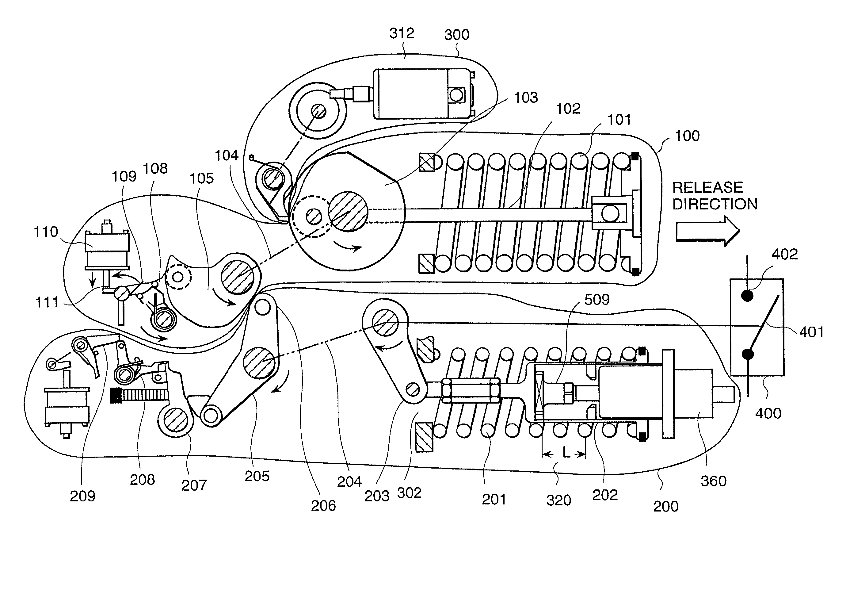
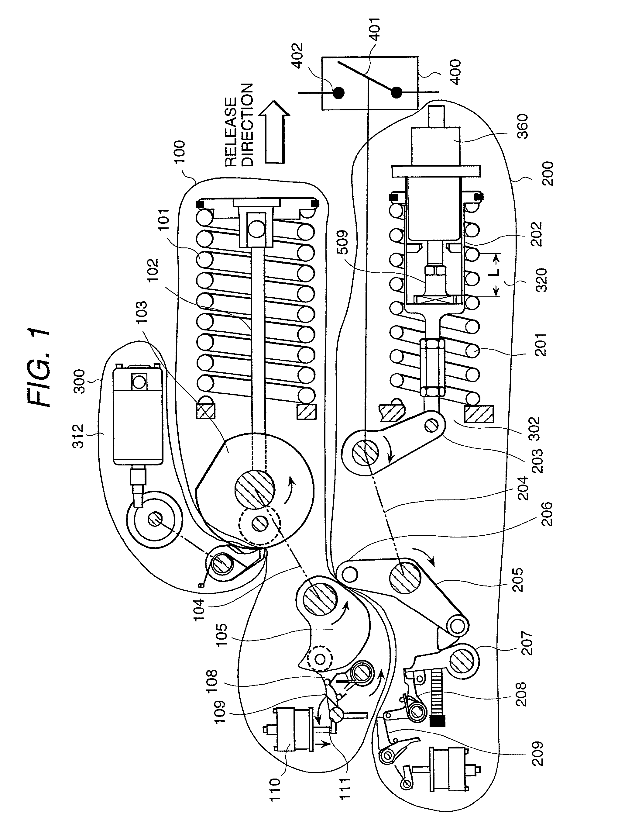
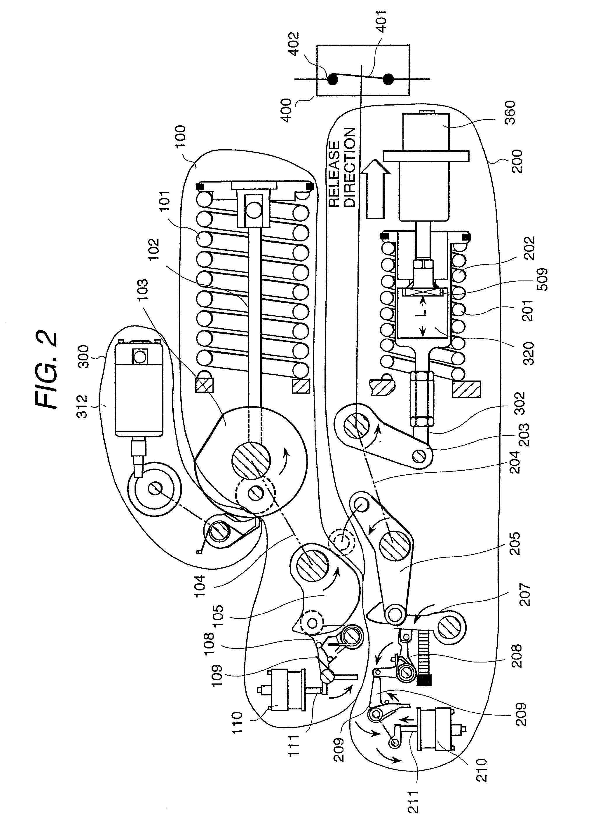
[0025] FIG. 6 shows a schematic construction of a preferred embodiment of the gas-insulated switch according to the present invention, wherein a fixed electrode 602 and a moving electrode 603, both constituting the breaking section of a circuit breaker, are connected to a fixed-side conductor 604 and a moving-side conductor 605, respectively. The fixed-side conductor 604 and moving-side conductor 605, supported respectively by the supporting insulators 606 and 607, are enclosed in a ground vessel 608 filled with arc-extinguishing gas. The supporting insulator 607, moving-side conductor 605 and moving electrode 603 are supported by an operating mechanism box 609 which houses the operating mechanism, to be explained later. The moving electrode 603 is connected to the output lever 203 of the operating mechanism, to be explained later, via an insulated opera...


PUM


Abstract

To reduce the size of a gas-insulated switch for the purpose of utilizing the space of a power station or substation effectively and improving the economy thereof. A gas-insulated switch equipped with a fixed contact and a moving contact that can contact with and separate from the fixed contact, wherein the breakage of the moving contact is operated with a single shock absorber in both the breaking action and the closing action of the moving contact. As a result that use of the gas-insulated switch according to the present invention improves the overall energy efficiency of components, a device with further reduced driving energy can be realized for a gas-insulated switch of the same specification.

Description

[0001] 1. Field of the Invention[0002] The present invention relates to a gas-insulated switch, particularly to a gas-insulated switch with a function of braking the inertial mass speed of the moving contact.[0003] 2. Prior Art[0004] Generally, a gas-insulated switch is equipped with a fixed contact and a moving contact for closing and breaking the main circuit of the power line so as to turn on and off the electricity. To break the main circuit, a break signal is sent to the operating device that drives the moving contact. Similarly, to connect the main line electrically, a close signal is sent to the operating device.[0005] As shown in FIG. 5, the moving portion of the switch, including the moving contact constituting the main circuit, makes accelerated motion and uniform motion, defined by the relationship among the drive force, load force and friction force, in the closing and breaking actions. At the last moment of each closing and breaking action, a suitable breakage is needed...

Claims


Application Information

Patent Timeline
Patent Type & Authority Applications(United States)
IPC IPC(8): H02B13/02H01H3/30H01H3/60H01H33/00H01H33/32H01H33/34H01H33/42
CPCH01H3/3015H01H3/3026H01H3/605H01H33/00
Inventor KAWAMOTO, HIDEOOKUBO, KENICHIISHIGURO, TETSU
Owner HITACHI LTD
Why Eureka
Try Eureka