Device and a method for continuous casting

a continuous casting and metal technology, applied in casting apparatus, metal-working apparatus, manufacturing tools, etc., can solve problems such as large problems, inability to accurately measure the effect of casting,

Inactive Publication Date: 2005-09-06
ABB (SCHWEIZ) AG
View PDF6 Cites 11 Cited by
  • Summary
  • Abstract
  • Description
  • Claims
  • Application Information

AI Technical Summary

Benefits of technology

[0009]The object of the present invention is to provide an apparatus and a method which make it possible to obtain, at least under certain casting conditions, a casting result which, at least in certain respects, is improved in relation to what is possible to achieve with prior art apparatuses and methods for continuous casting of metals.
[0013]Consequently, through the apparatus according to the invention, a braking of the downward movement of the melt, adapted to the value prevailing of one or more said casting parameters, may be performed by means of the first-mentioned magnetic member, which permits the above-mentioned bubbles to rise to the upper surface and be removed and not be incorporated in the solidified portion of the strand, while at the same time the secondary flow upwards at the short ends of the strand may be stabilized for stable supply of hot melt to the meniscus and energy addition thereto. Further, the last-mentioned magnetic member adapted to generate a variable magnetic field can ensure that the movements of the melt in the area of the upper surface thereof, especially in said central region, are the most suitable movements at a value prevailing of one or more of said predetermined casting parameters, for achieving, over the whole cross section of the casting mould, an essentially uniform speed of the melt at the upper surface and hence a uniform, stable temperature of the upper surface of the melt.
[0015]By arranging such magnetic members, movements of the molten material in the area of said upper surface may be braked in said end regions to an extent that is optimal for the prevailing conditions on each individual casting occasion, that is, the value prevailing of one or more predetermined casting parameters. This implies that the possibilities of achieving a uniform desired movement and a uniform, stable temperature of the upper surface of the melt are improved. Especially in the case of casting speeds in an intermediate range and at higher casting speeds, it may be important to brake the movements of the molten material in the area of the upper surface in these end regions, whereas such braking may be made very slight or be completely eliminated at lower casting speeds by controlling the strength of the stationary magnetic field down towards zero.
[0016]According to a preferred embodiment of the invention, the apparatus according to the invention comprises both the magnetic members according to the first aspect of the invention and the magnetic members according to the second aspect of the invention. This then leads to possibilities of achieving a flow rate of the melt in various parts of the casting mould which is optimal for the casting result, both deeper downwards in the casting mould and upwards in the casting mould, and in the area of the upper surface, as well as a uniform, stable temperature and movement of the upper surface of the melt irrespective of the casting speeds occurring. In other words, with one and the same apparatus, an excellent casting result may be obtained at low casting speeds, when the melt in the area of the upper surface needs to be stirred, above all near the casting pipe, and be accelerated, at casting speeds in an intermediate range, when hot molten material needs to be supplied to the area of the upper surface from the casting jet, stirring in the area of the upper surface around the casting pipe is needed and the movements of the melt in the area of the upper surface must be braked somewhat to obtain a maximum flow rate in the upper surface, and at high casting speeds, when the braking of the upper surface must be strong to achieve an optimum speed of the melt in the area of the upper surface, while at the same time no stagnation zones are allowed to arise centrally around the casting pipe.
[0021]According to another preferred embodiment of the invention, the unit is adapted, at determined values of one or more of said predetermined casting parameters, to control said members for generating a magnetic field in the area of the upper surface in said central region to alternately generate a so-called alternating field, changing in time, for stirring the molten metal and a stationary magnetic field for braking the movements of the molten metal. In this way, under certain casting conditions, a very good temperature equalization of the melt in the area of the upper surface of the molten bath may be obtained.

Problems solved by technology

This results in inclusions and irregularities of the finished, solidified cast strand.
These problems become especially great in the case of high casting speeds, that is, when a large volume of molten material is supplied to the casting mould per unit of time.
This also entails a considerable risk of irregular speeds of the movements of the molten material in the area of the upper surface of the bath and of resultant pressure variations at the upper surface, and a risk that variations in height may occur in the upper surface.
At high casting speeds, this leads to slag being drawn down, uneven slag thickness, uneven shell thickness, and a risk of formation of cracks.
There is also a risk of oscillations of the molten material in the casting mould leading to an unsymmetrical speed of the cast material downwards in the mould, such that the speed at one side becomes considerably higher than the speed at the other side.
This results in a considerable transport downwards of inclusions and gas bubbles with an ensuing deteriorated slabs quality.
This is, therefore, of interest especially at lower casting speeds, since there is then a risk that the movement of the cast material in the area of the upper surface will be too small and that temperature differences, which have a negative influence on the casting result, may arise.

Method used


Image

  • Device and a method for continuous casting
  • Device and a method for continuous casting
  • Device and a method for continuous casting

Examples


Embodiment Construction

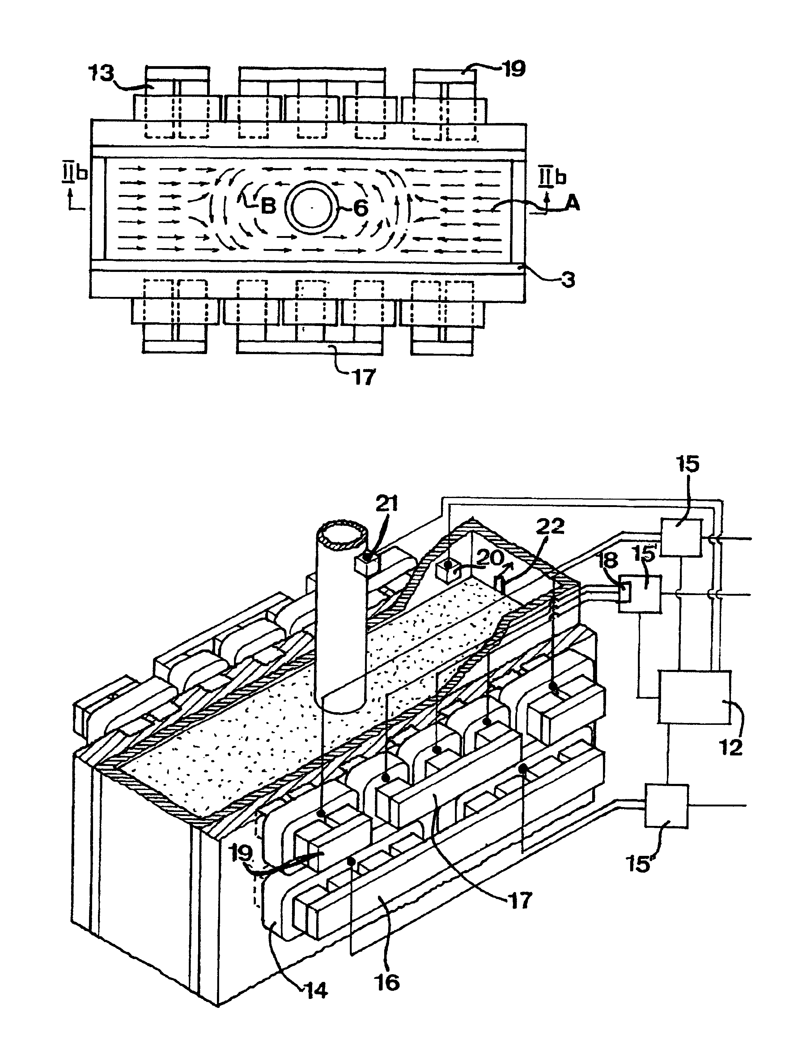
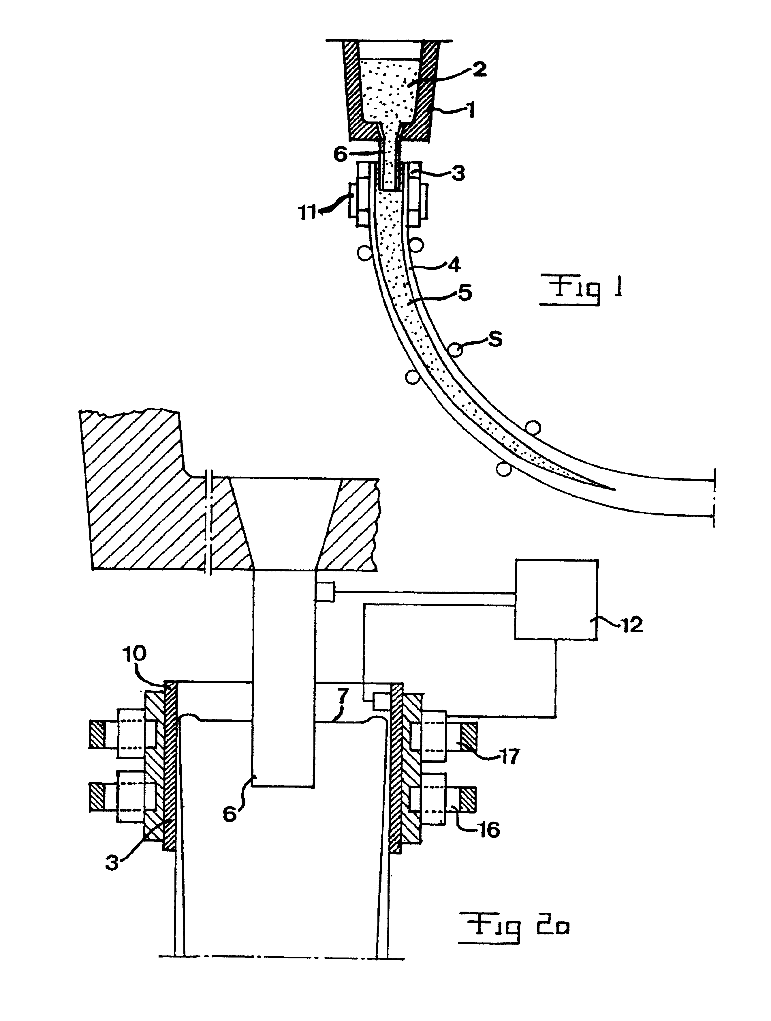
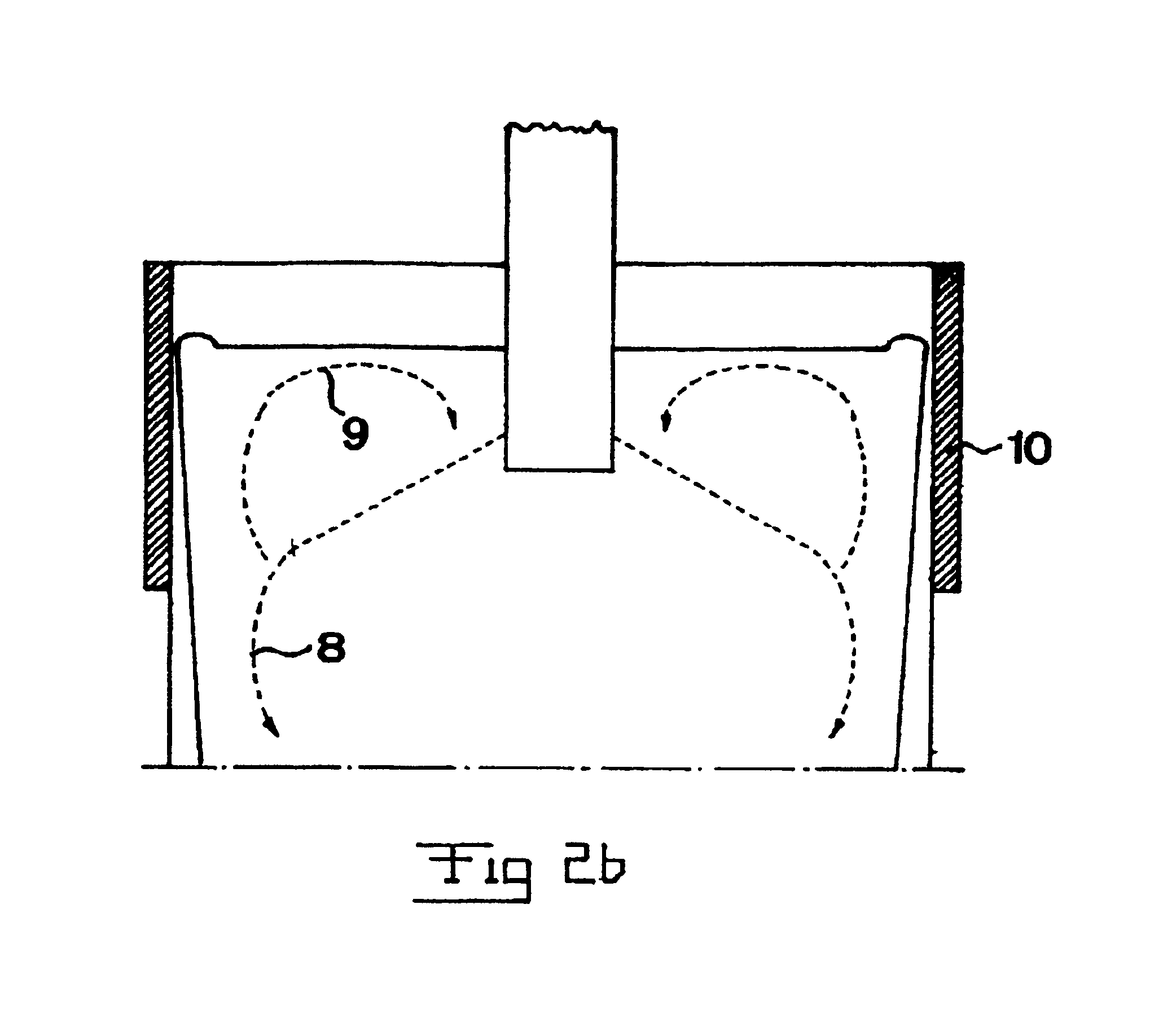
[0034]The principles of the invention will now be described with reference to FIGS. 2-4, which in a simplified manner illustrate an apparatus for continuous casting of metals according to a first preferred embodiment of the invention. As previously stated, the casting mould 3 has an elongated horizontal cross section, and in practice this normally means a considerably smaller relation of length of the short side to length of the long side than what is shown in the figures, and in this respect the figures are only to be interpreted as explaining the principles of the invention. Thus, the thickness of the strand may, for example, be of the order of magnitude of 150 mm while at the same time its width is over 1,500 mm.

[0035]The molten metal that is supplied to the casting mould has a certain overtemperature, that is, the temperature thereof must be lowered to a certain extent in order for any part thereof to start solidifying. This is important in order to avoid that solidification of ...


PUM

PropertyMeasurementUnit
frequencyaaaaaaaaaa
widthaaaaaaaaaa
widthaaaaaaaaaa

Abstract

An apparatus for continuous casting of metals has members (16) adapted to generate a stationary magnetic field of a variable strength over substantially the entire horizontal cross section of the mould from one long side to the other long side close to, or below, the region for supply of molten metal at a distance below the upper surface of the molten metal. There are also members (17) adapted to generate a variable magnetic field in the area of the upper surface in a region that is centrally located with respect to said cross section and close to a region for supply of molten metal. A unit (12) is adapted to control said magnetic members (16, 17) to generate, independently of each other, magnetic fields with an appearance that is dependent on the value prevailing of one or more predetermined casting parameters.

Description

FIELD OF THE INVENTION AND BACKGROUND ART[0001]The present invention relates to a method and an apparatus for continuous casting of metals, comprising a casting mould with an elongated horizontal cross section, through which a molten metal is intended to pass during the casting operation, a member for supplying a molten metal to such molten metal already present in the casting mould in a region at a distance below the upper surface of the latter melt, and a device adapted to apply magnetic fields to the melt in the casting mould to influence movements of the molten material.[0002]An apparatus of the above-mentioned type is illustrated schematically in the accompanying FIG. 1. From a so-called tundish 1, a molten metal 2 is supplied to a casting mould 3 in the form of a box, open at the top and at the bottom, having cooled walls, usually of a copper-based alloy with a good thermal conductivity. The cooling in the casting mould causes the solidification of the elongated strand, formed...

Claims


Application Information

Patent Timeline
Patent Type & Authority Patents(United States)
IPC IPC(8): B22D11/11B22D11/115B22D11/16B22D46/00
CPCB22D11/115
Inventor ERIKSSON, JAN-ERIK
Owner ABB (SCHWEIZ) AG
Why Eureka
Try Eureka