Method for hydrothermally reducing CO2 or CO into methane by using porous nickel catalyst

A catalyst and porous nickel technology, applied in the field of environmental engineering, can solve problems such as catalyst bed temperature fluctuations, unfavorable industrial applications, and reduced conversion efficiency, and achieve the effects of solving energy shortages, facilitating reaction temperature, and controlling reaction temperature

Inactive Publication Date: 2012-05-23
TONGJI UNIV
View PDF2 Cites 7 Cited by
  • Summary
  • Abstract
  • Description
  • Claims
  • Application Information

AI Technical Summary

Problems solved by technology

First, the semiconductor-based colloidal catalytic system and noble metal complex solution catalytic system have the disadvantages of low catalytic efficiency and low quantum yield, and the high cost of such catalysts is not conducive to industrial applications
The second is that mercury lamps are mostly used to simulate sunlight in laboratory research, but the actual sunlight is more dispersed than mercury lamp radiation, so the reaction device needs to have a large light-receiving area to gather sunlight on a large scale, which will inevitably increase the cost
Although the gas-phase reduction of carbon dioxide has been widely used in industry at present, there are still some problems in this method, which are embodied in: (1) when the CO content in the feed gas>0.3%, (CO+CO 2 )>0.7%, it is easy to cause the catalyst bed temperature to fluctuate, and it is difficult to control the temperature accurately
(2) The methanation reaction is carried out in the gas phase, which is prone to carbon deposition, resulting in catalyst deactivation and lower conversion efficiency

Method used


Image

  • Method for hydrothermally reducing CO2 or CO into methane by using porous nickel catalyst
  • Method for hydrothermally reducing CO2 or CO into methane by using porous nickel catalyst
  • Method for hydrothermally reducing CO2 or CO into methane by using porous nickel catalyst

Examples


Embodiment 1

[0024] The exhaust gas of coal-fired power plants is CO 2 One of the main sources of emissions. Currently, China's power sector emits 2.7 billion tons of CO2 per year 2 It ranks second in the world after the United States. Applying the present invention to the power sector, the waste CO emitted by it can be 2 The collection is passed into a hydrothermal reactor for treatment. Moreover, the waste heat of the power plant can provide the temperature required for some reactions, so that the energy consumption of hydrothermal treatment of carbon dioxide can be reduced.

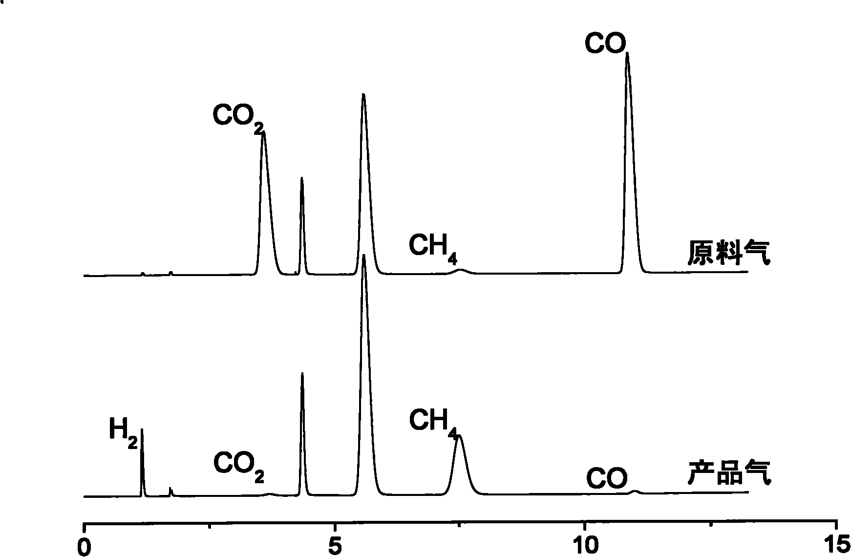
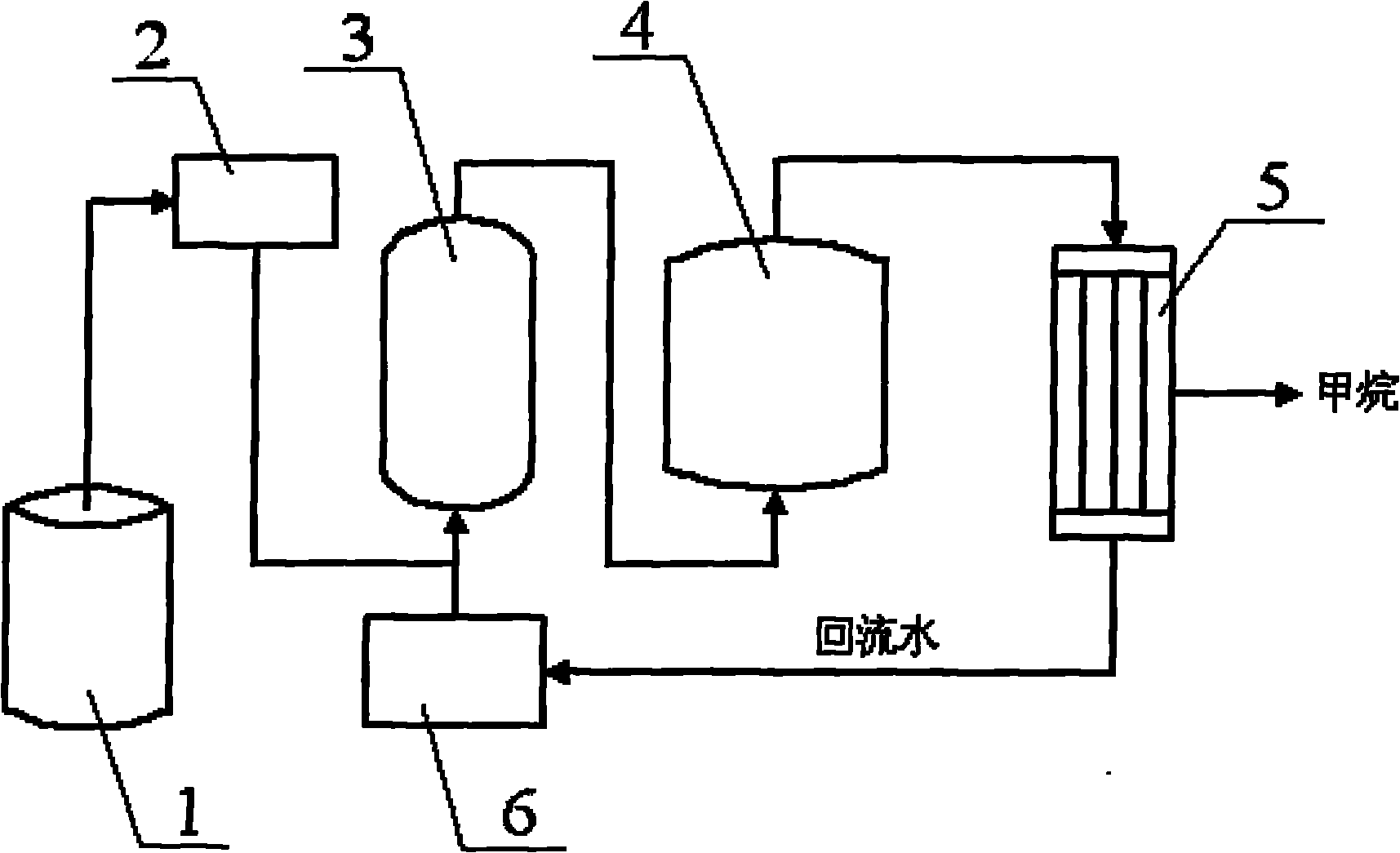
[0025] Coal-fired power plants use appropriate hydrothermal reactors according to requirements, and their industrial production can adopt the process flow shown in the attached figure. The reaction conditions are controlled as follows: the amount of hydrogen added is CO 2 5 times (in molar ratio), the reaction temperature is 300° C., the reaction pressure is 10 MPa, the ratio of catalyst addition to feed gas i...

Embodiment 2

[0028] The average operating efficiency of coal-fired industrial boilers is only 60% to 65%. The annual emission of soot is about 2 million tons, sulfur dioxide is about 7 million tons, and carbon dioxide is nearly 1 billion tons. It is the second largest source of soot pollution after thermal power plants. . In response to this situation, hydrothermal reaction devices can be installed in each coal-fired plant to collect and process the exhaust gas emitted by it.

[0029] Coal-fired industrial boilers use appropriate hydrothermal reactors according to their specifications, and their industrial production can adopt the process flow shown in the attached figure. The reaction conditions are controlled as follows: the amount of hydrogen added is CO 2 5 times (in molar ratio), the reaction temperature is 350° C., the reaction pressure is 10 MPa, the ratio of catalyst addition to feed gas is 1:1 (molar ratio), and the reaction time is 60 minutes.

[0030] Through this reaction, CO...

Embodiment 3

[0032] Emissions of greenhouse gases such as carbon dioxide from waste incineration plants are increasing, and it has been calculated that most incinerators produce more carbon dioxide per year than thermal power plants. For the large amount of carbon dioxide contained in the flue gas, a hydrothermal treatment equipment can be built on site to collect the discharged waste gas and use it as raw material for hydrothermal conversion. Moreover, the large amount of heat energy brought by incineration can fully provide the temperature required for the reaction, which further reduces the operating cost of hydrothermal treatment of carbon dioxide.

[0033] The waste incineration plant adopts suitable hydrothermal reactors according to the requirements, and its industrial production can adopt the process flow shown in the attached figure. The reaction conditions are controlled as follows: the amount of hydrogen added is CO 2 10 times (in molar ratio), the reaction temperature is 200°C...


PUM


Abstract

The invention relates to a method for hydrothermally reducing CO2 or CO into methane by using a porous nickel catalyst. The method comprises the following steps of: placing the porous nickel catalyst into a hydrothermal reactor, mixing hydrogen and CO2 or CO according to the molar ratio of 1:(1-10) in the hydrothermal reactor, controlling the temperature of the reactor to 200 to 400 DEG C, and adjusting the pressure of the reactor to 6 to 20MPa and the reaction time to 5 to 180 minutes to obtain the reaction product, namely methane. When the method is compared with the prior art, the highest conversion rate of CO2 and CO is 99 percent, the whole reaction is performed under a hydrothermal condition, the defect that the catalyst is inactivated because carbon is easy to accumulate on the surface of the catalyst in a gas-phase reduction process is overcome, and the used catalyst has the characteristics of high strength, good activity, good thermal stability, excellent low-temperature activity and the like.

Description

technical field [0001] The invention relates to the technical field of environmental engineering, in particular to a method for hydrothermally reducing CO using a porous nickel catalyst. 2 method for methane. Background technique [0002] Since the 1930s, human use of fossil fuels has emitted large amounts of CO 2 Greenhouse gases such as CO in the atmosphere 2 The problem of continuous increase in concentration has attracted great attention from governments of various countries. How to limit CO 2 Excessive emissions have become a global issue for the sustainable development of countries. Therefore from CO 2 The conversion technology from chemical to chemical has attracted the attention of countries all over the world and has begun to be put into practical application. At present, technological achievements at different development stages have been produced, such as the utilization of CO with the direct or indirect participation of other chemical substances 2 The techn...

Claims


Application Information

Patent Timeline
Patent Type & Authority Applications(China)
IPC IPC(8): C07C9/04C07C1/04C07C1/12B01D53/86B01D53/62
CPCY02A50/20
Inventor 金放鸣闫鹏崔欣程敏
Owner TONGJI UNIV
Why Eureka
Try Eureka