Crude rubber production system

A production system and raw rubber technology, applied in the field of raw rubber production system, can solve the problems of polluted materials, glue filaments easy to adhere to the kettle wall, troublesome mass production, etc.

Active Publication Date: 2011-09-28
LIYANG LIDA SILICONE TECH
View PDF5 Cites 7 Cited by
  • Summary
  • Abstract
  • Description
  • Claims
  • Application Information

AI Technical Summary

Problems solved by technology

Ordinary low-molecular rubber removal device, due to the conversion of vacuum and positive pressure, the rubber thread is easy to adhere to the wall of the kettle, accumulating over time, forming dead glue under long-term high temperature, which will affect heat transfer and affect the effect of removing low molecular weight
Once the dead glue is formed, the system must be dismantled and washed immediately, and dismantling and washing takes time (usually 1 week) and also pollutes materials, resulting in a lot of waste and high cost
In addition, the ordinary raw rubber removal device adopts steam coil heating, and the temperature will change with the change of steam pressure. The temperature is controlled by fast and frequent adjustment valves, and the temperature fluctuation is unstable, which will affect the removal effect of low molecules. larger
[0007] After the process of removing low molecular weight, the temperature of raw rubber is generally 160~170°C. If it is not cooled, it cannot be packaged directly. It can only be discharged into metal containers first, and then packed in plastic bags and cartons after cooling. , high cost, low efficiency, easy to pollute, and troublesome for large-scale production

Method used


Image

  • Crude rubber production system
  • Crude rubber production system
  • Crude rubber production system

Examples


Embodiment 1)

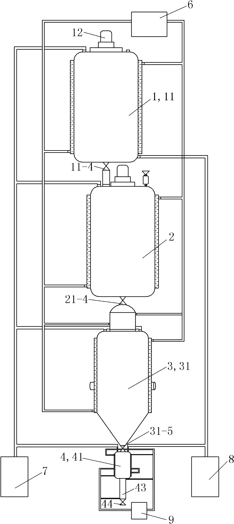
[0076] See figure 1 As shown in Figure 14, the raw rubber production system of this embodiment includes a raw rubber dehydration device 1, a raw rubber polymerization reaction device 2, a raw rubber removal low molecular device 3, a raw rubber receiver and a rubber output device 4, and a hot oil circulation heating device 6. Vacuumizing device 7, nitrogen supply device 8 and cooling water circulation cooling device 9.

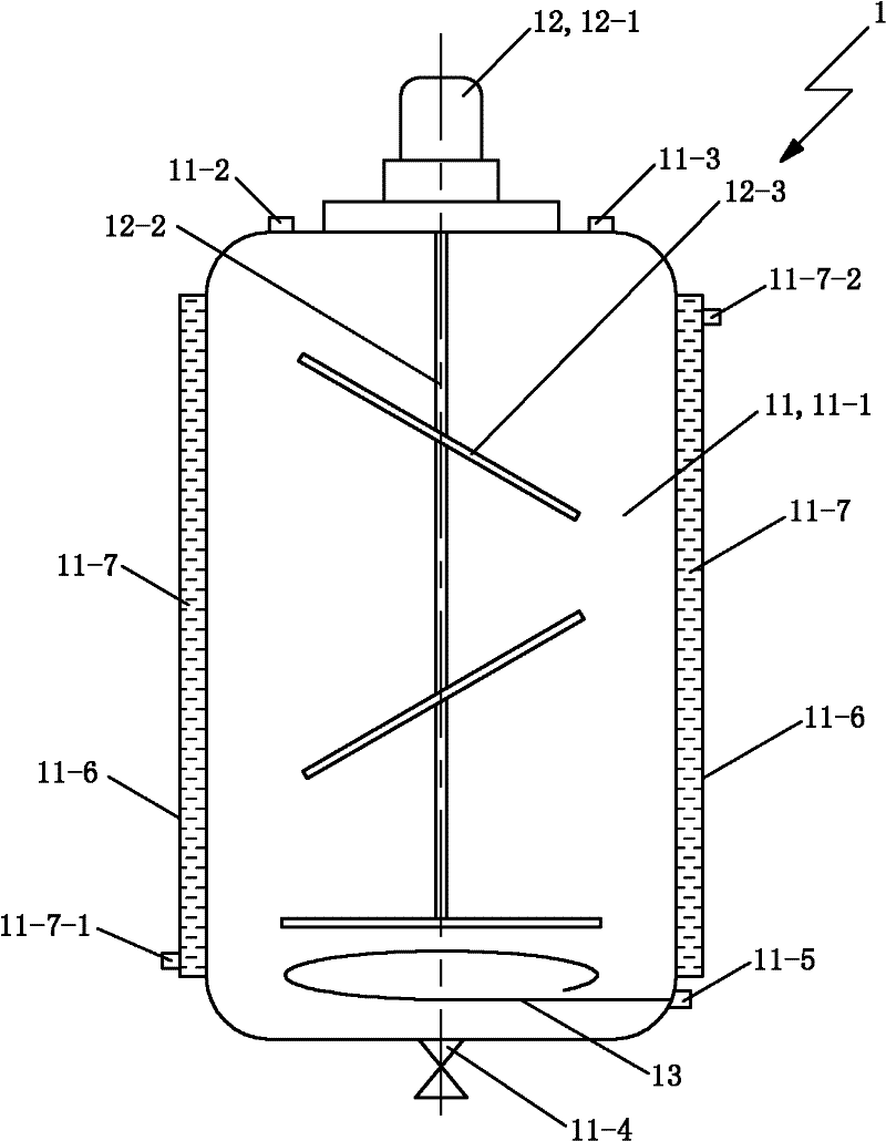
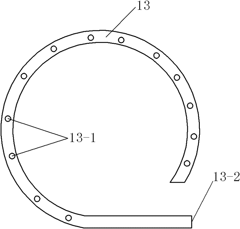
[0077] See figure 2 , The raw rubber dehydration device 1 includes a dehydration kettle 11 , a dehydration kettle stirring mechanism 12 and a nitrogen coil 13 .

[0078] The dehydration kettle 11 includes a dehydration kettle body 11-1, a dehydration kettle vacuum interface 11-2, a dehydration kettle feeding interface 11-3, a first discharge valve 11-4, a nitrogen delivery interface 11-5 and a dehydration kettle. Kettle jacket plate 11-6. The dehydration kettle jacket plate 11-6 and the dehydration kettle body 11-1 together constitute the dehydration kettle...


PUM

PropertyMeasurementUnit
pore sizeaaaaaaaaaa

Abstract

The invention relates to a crude rubber production system which comprises a crude rubber dehydration device, a crude rubber polymerization reaction device, a crude rubber low-molecular removal device, a crude rubber receiver, a rubber discharge device, a hot oil circulation heating device, a vacuuming device, a nitrogen feeding device and a cooling water circulation cooling device, wherein the hot oil circulation heating device is communicated with the clamp sleeve of the dehydration kettle of the crude rubber dehydration device, the clamp sleeve of the reaction kettle of the crude rubber polymerization reaction device, the clamp sleeve of the devolatiligation kettle of the crude rubber low-molecular removal device and the tubulation preheater of the crude rubber low-molecular removal device; the vacuuming device is communicated with the dehydration kettle of the crude rubber dehydration device, the reaction kettle of the crude rubber polymerization reaction device, the devolatiligation kettle of the crude rubber low-molecular removal device and the tank bodies of the crude rubber receiver and the rubber discharge device; the nitrogen feeding device is communicated with a nitrogen transportation connector piece in the dehydration kettle and the tank bodies of the crude rubber receiver and the rubber discharge device; and the water inlet and water outlet of the cooling water circulation cooling device are communicated with the cooling disks of the crude rubber receiver and the rubber discharge device and a tabulation cooler.

Description

technical field [0001] The invention relates to a raw rubber production system. Background technique [0002] Silicone rubber has good electrical insulation, oxygen and aging resistance, light resistance and aging resistance, mildew resistance, chemical stability, etc., and is odorless and non-toxic, and can withstand high and low temperatures. It is widely used in rubber, plastics, coatings, etc. , adhesives, sealants and other polymer industries, and also play an important role in the medical field. [0003] In the preparation process of silicone rubber, dimethylcyclosiloxane is used as the main raw material, and methyl vinyl tetracycline accounting for 1 / 1000 to 4 / 1000 of dimethylcyclosiloxane is added, Under the action of catalyst, dimethyl cyclosiloxane undergoes open-chain polymerization reaction to generate high-molecular linear dimethyl polysiloxane, and methyl vinyl tetracyclic body also undergoes open-chain polymerization reaction to generate high-molecular polysi...

Claims


Application Information

Patent Timeline
Patent Type & Authority Applications(China)
IPC IPC(8): C08G77/06C08G77/34
Inventor 张国年陈拉克
Owner LIYANG LIDA SILICONE TECH
Why Eureka
Try Eureka