Eureka AIR delivers breakthrough ideas for toughest innovation challenges, trusted by R&D personnel around the world.

Molding device for the production of containers in thermoplastic material

a thermoplastic material and molding device technology, applied in dough shaping, baking, food shaping, etc., can solve the problems of increasing the weight of the half-mold and also their cost, heavy and expensive, and the sliding and accommodating slots are not easy to be re-used, so as to reduce the weight of the mold. , the effect of reducing the number of times

Inactive Publication Date: 2008-05-27
SIDEL PARTICIPATIONS SAS
View PDF5 Cites 11 Cited by
  • Summary
  • Abstract
  • Description
  • Claims
  • Application Information

AI Technical Summary

Benefits of technology

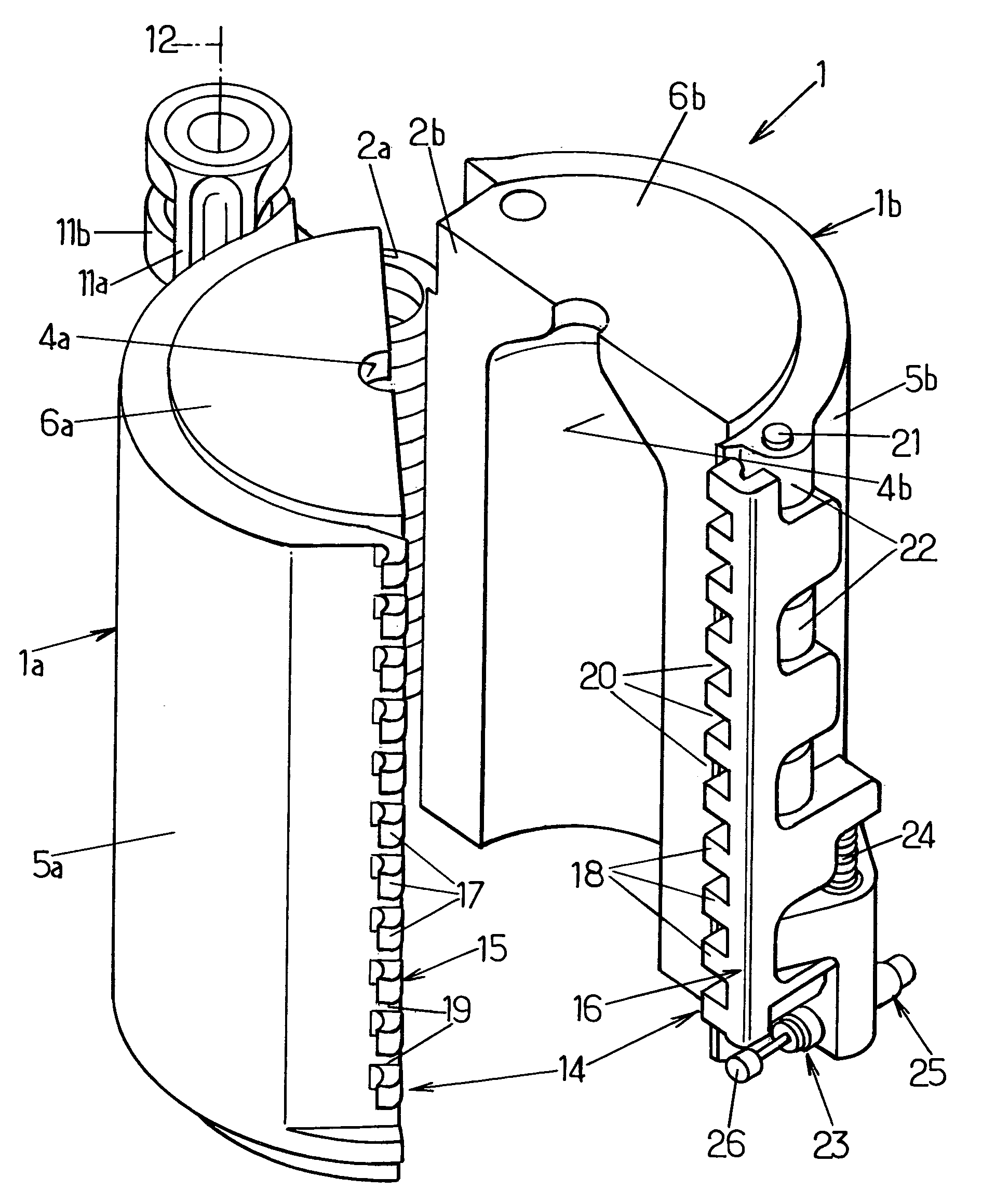
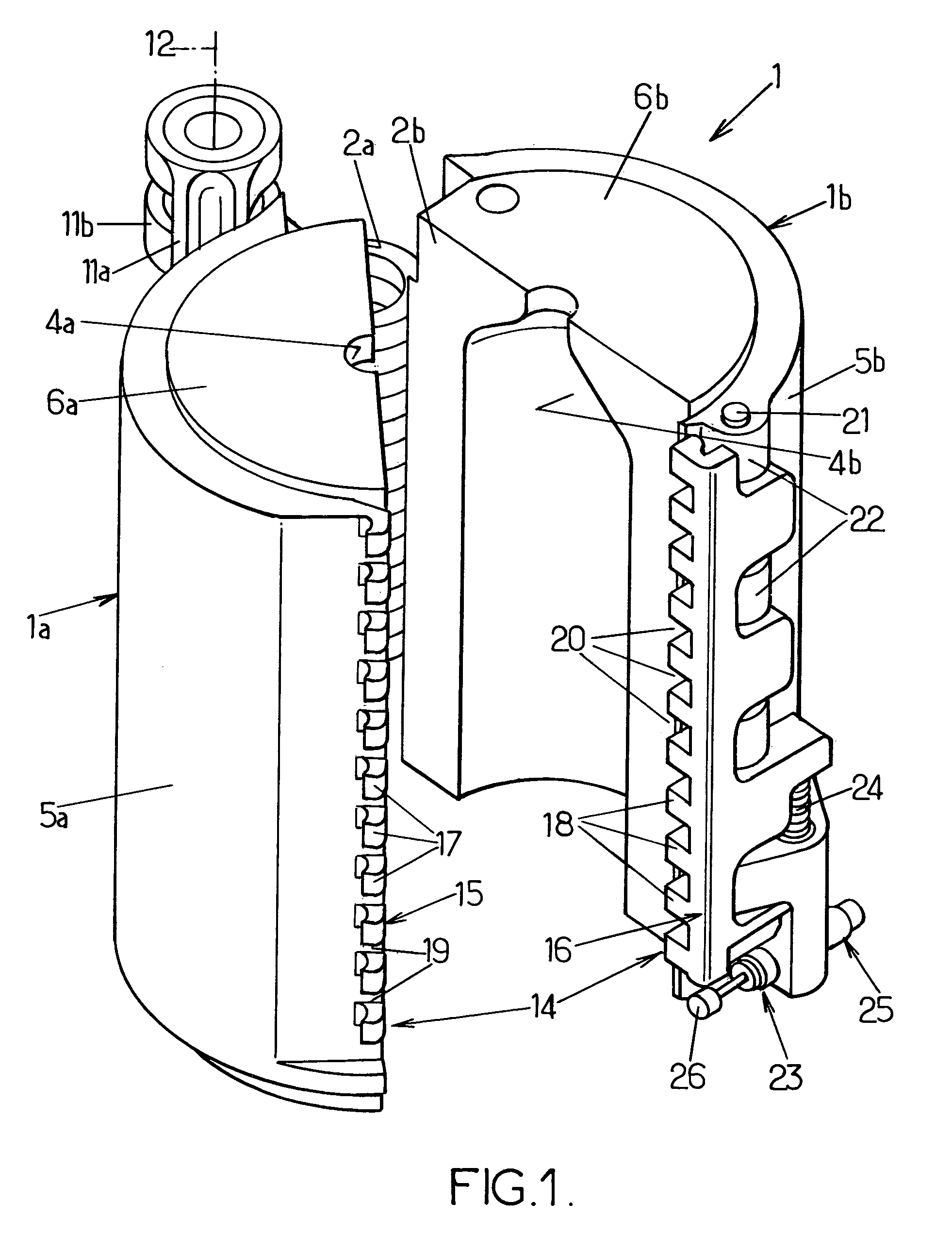
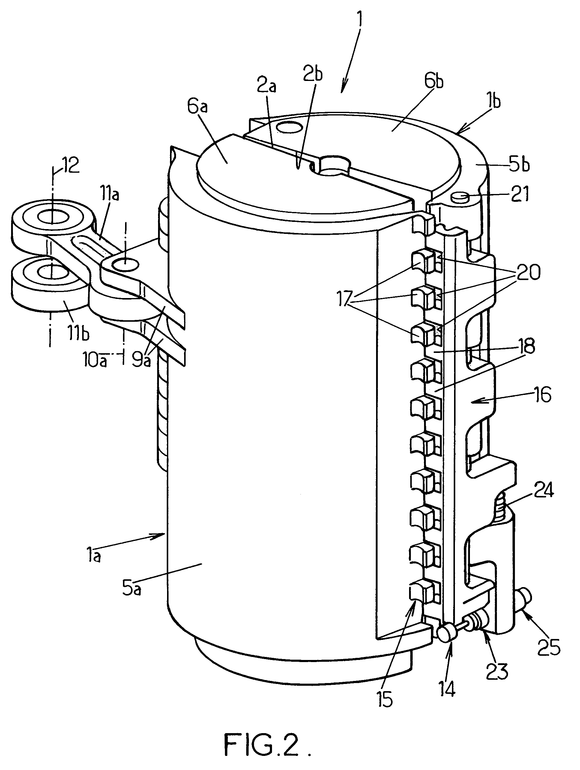
[0018]In order to obtain a uniform distribution of the catching force over the entire height of the mold, it is desirable for the number of fingers to be as high as possible in relation to the mechanical strength of said fingers, whereby the height of the spacings between the fingers and therefore the travel of the moving lock element between its locked and unlocked positions are as low as possible, which allows for more rapid closure than can be obtained with the conventional mechanisms when the blowing device is a rotary one.
[0027]By virtue of the provisions according to the invention, a blow-molding or stretch-blow-molding mold is produced in which locking is obtained by a single moving part with a relatively short travel; this travel is linear and parallel to the axis of the mold; finally, the moving part, which is greatly notched in many places to define the locking fingers, has a low mass and therefore a low inertia.
[0028]The result of this is that no angular movement of the locking parts is superposed on the rotational movement of the half-molds during closure or opening and these half-molds are subjected to no parasitic acceleration as they rotate. The vertical movement component of the moving lock element has no appreciable influence over the behavior of the corresponding half-mold. This then finally yields more uniform movements of the half-molds and, above all, shorter locking / unlocking times that provide an effective contribution to increasing the operating rate of the molding device; indeed, for the same rotational speed, if the times needed for locking / unlocking are shorter, the time available for blowing can be increased.

Problems solved by technology

However, these locking means do have several significant disadvantages.
One disadvantage lies in the fact that the fingers and accommodating slots are supported in cantilever fashion by the first and second half-molds respectively.
To prevent them from deforming or pulling out, these supports need to be solidly formed, and this increases the weight of the half-molds and also their cost.
Another disadvantage lies in the cantilevered structure of each finger, the base of which is set into a radially projecting support secured to one half-mold whereas, in the locked position, the free end of the finger is held in a corresponding accommodating slot of a radially projecting support secured to the other half-mold.
Under the blowing force, each finger is subjected to a bending / shear stress which, once again, entails that each finger be solidly formed, making it heavy and expensive.
All these requirements lead to locking means that project appreciably from the periphery of the mold whereas, in installations comprising a great many molds and operating at high speed (rotary molding devices of the carousel type), the space available is very restricted.
Furthermore, these locking means are heavy and increase the inertia of the half-molds, something which is detrimental to installations operating at high speed.
This then finally results in a non-uniform distribution of the forces over the height of the mold.

Method used


Image

  • Molding device for the production of containers in thermoplastic material
  • Molding device for the production of containers in thermoplastic material
  • Molding device for the production of containers in thermoplastic material

Examples


Embodiment Construction

[0033]The arrangements according to the invention are improvements made to molding devices for the blow-molding or stretch-blow-molding of containers, such as bottles, from heated thermoplastic (for example PET) preforms. Such a molding device comprises at least one mold comprising at least two half-molds (and possibly a third part that forms an axially movable mold bottom) which can be moved relative to one another between an open position in which they are parted from one another and a closed position in which they are pressed firmly against one another by collaborating respective faces defining a parting line, locking means being provided to lock the two half-molds in the closed position and prevent them from parting or gaping when the blowing fluid is introduced under very high pressure (for example typically of the order of 40×105 Pa).

[0034]Commonly, such molding devices may comprise a multiplicity of molds and may therefore be arranged in the form of a rotary device or carouse...


PUM

PropertyMeasurementUnit
blowing pressureaaaaaaaaaa
pressureaaaaaaaaaa
heightaaaaaaaaaa

Abstract

A moulding device for the production of containers in thermoplastic material, by blowing or blow-drawing, including a mould with two mould halves mutually mobile and provided with a locking device with two lock elements extending over the total height of the respective mould halves and provided with a number of projecting fingers in catches spaced at intervals, one lock element being fixed on one mould half and the other lock element sliding on the other mould half under the action of an actuator device.

Description

FIELD OF THE INVENTION[0001]The present invention relates in general to the field of molding devices for blow-molding or stretch-blow-molding containers from heated thermoplastic preforms.[0002]More specifically, the invention relates to improvements made to those of these devices that comprise at least one mold comprising at least two half-molds that can be moved with respect to each other between an open position in which they are parted from one another and a closed position in which they are firmly pressed against one another via collaborating respective bearing faces defining a parting line, locking means being provided to lock the two half-molds in the closed position, which locking means comprising on at least one side of the mold, a first lock element in the form of a hook secured fixedly to the first half-mold along the edge of the bearing face thereof, a second lock element in the form of a hook inverted with respect to the previous one and mounted such that it can move on...

Claims


Application Information

Patent Timeline
Patent Type & Authority Patents(United States)
IPC IPC(8): B29C49/56B29C33/26B29C49/06B29C49/12B29C49/36
CPCB29C33/26B29C49/56B29C49/06B29K2067/00B29C49/36B29C49/12B29C2049/023B29C2049/5662B29C2949/0715B29C2049/7831B29C33/20B29C49/08
Inventor LEMAISTRE, ERICLEBLOND, REGIS
Owner SIDEL PARTICIPATIONS SAS
Why Eureka
Eureka Blog
Learn More