Municipal drainage system

A municipal drainage system and drainage channel technology, which is applied to waterway systems, sewer systems, drainage structures, etc., can solve the problems of drainage system blockage, waterlogging, and low level, and achieve the effects of improving drainage efficiency, strong practicability, and ingenious design

Pending Publication Date: 2022-01-28
黄珺
View PDF7 Cites 0 Cited by
  • Summary
  • Abstract
  • Description
  • Claims
  • Application Information

AI Technical Summary

Problems solved by technology

[0002] The municipal drainage system can also be called the urban drainage system. It refers to the engineering facility system for treating and removing urban sewage and rainwater. It is an integral part of urban public facilities. Urban drainage system planning is an important part of urban overall planning, usually by It is composed of drainage pipes and sewage treatment plants. In the case of sewage and rainwater separation system, sewage is collected by drainage pipes, sent to sewage treatment, and then discharged into water bodies or recycled. Rainwater runoff is collected by drainage pipes and discharged into nearby water bodies. , while the existing drainage pipe entrances are mostly rainwater inspection manhole covers for sealing and filtering, and the tanks provided on it to supply rainwater to leak into the pipes are mostly slender structures, which can block larger debris in the drainage In order to prevent pipeline blockage, but the existing manhole cover can not intercept small impurities, these impurities will cause blockage of the drainage system when they enter the drainage system with the water flow, and then cause the ground to produce water accumulation or even waterlogging, etc. At this time, the staff will choose to install a filter screen in the pipe of the drainage system or at the open end. Although this method can prevent impurities from entering the depth of the drainage system, the accumulation will still cause blockage, and the staff will have to Frequent sewage dredging is time-consuming, laborious and inefficient. In view of this, we propose a municipal drainage system

Method used


Image

  • Municipal drainage system
  • Municipal drainage system
  • Municipal drainage system

Examples


Embodiment Construction

[0023] see Figure 1-7 , the present invention provides a kind of technical scheme:

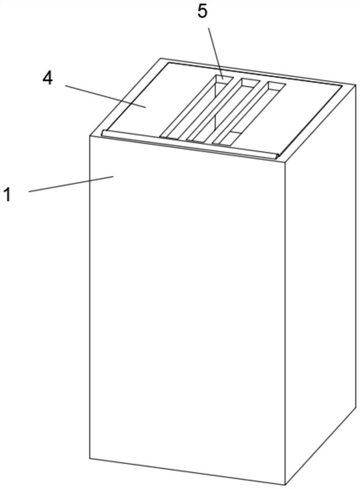
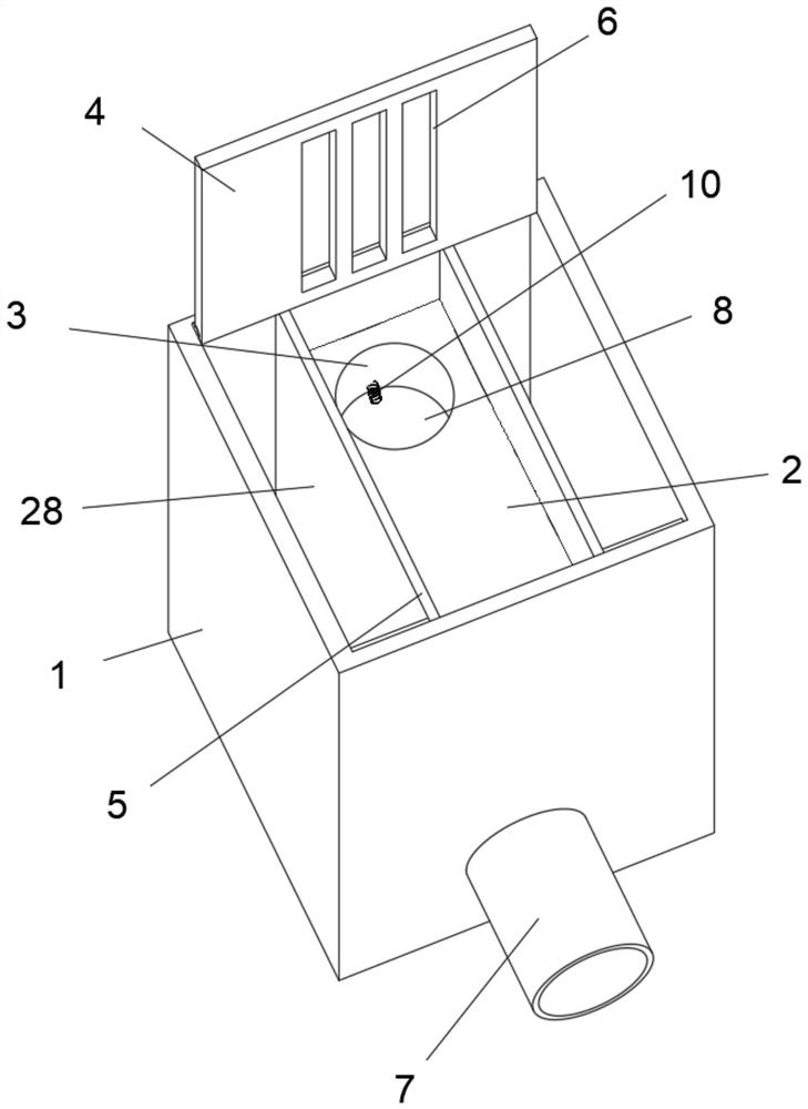
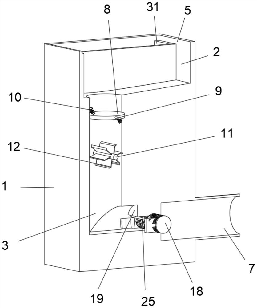
[0024] A municipal drainage system, comprising a shell 1, a water tank 2 is opened in the middle of the top surface of the shell 1, a drainage channel 3 is opened at the front end of the bottom surface of the water tank 2, a square cover 4 is hinged at the front end of the top surface, and the position of the top surface of the shell 1 relative to the square cover 4 is opened There is a square tank 5, and the middle part of the square cover 4 is linearly and equally spaced with respect to the position of the water tank 2, and a plurality of water leakage ports 6 are provided. The middle part of the baffle plate 8 is provided with an axis 9, and the upper and lower outer walls of the baffle plate 8 have a centrally symmetrical structure and are fixed with two tension springs 10. A plurality of dials 12, a cavity 13 is provided inside the housing 1 relative to the left end of the rotating shaf...


PUM


Abstract

The invention discloses a municipal drainage system and belongs to the technical field of municipal drainage. The municipal drainage system comprises a shell, wherein a water tank is formed in the middle of a top face of the shell, a guide rod is fixedly arranged at the position, opposite to an upper end of the front side of a movable plate, in a drainage channel, and drain outlets are formed in the positions, opposite to the movable plate, of the inner walls of the two sides of the drainage channel; collecting grooves are formed in the positions, opposite to the outer side end of the sewage draining outlet, of the two sides in the shell, a pressing plate is arranged on a top face of the outer side of a sealing plate, a pulling plate is fixedly arranged at a rear end of a top face of the pressing plate, and a bottom face of the sealing plate and bottom faces of the collecting grooves are each of a front-back symmetrical structure and provided with two round cavities; a compression spring is fixedly arranged between the interiors of the two circular cavities located on the same side. The energy of flowing water can be fully utilized, a phenomenon that impurities are accumulated on the front side of a roller to block water flow loss is avoided through back-and-forth movement of the movable plate, drainage efficiency of the drainage system is greatly improved, and water accumulation and waterlogging are avoided.

Description

technical field [0001] The invention relates to the technical field of municipal drainage, more specifically, to a municipal drainage system. Background technique [0002] The municipal drainage system can also be called the urban drainage system. It refers to the engineering facility system for treating and removing urban sewage and rainwater. It is an integral part of urban public facilities. Urban drainage system planning is an important part of urban overall planning, usually by It is composed of drainage pipes and sewage treatment plants. In the case of sewage and rainwater separation system, sewage is collected by drainage pipes, sent to sewage treatment, and then discharged into water bodies or recycled. Rainwater runoff is collected by drainage pipes and discharged into nearby water bodies. , while the existing drainage pipe entrances are mostly rainwater inspection manhole covers for sealing and filtering, and the tanks provided on it to supply rainwater to leak int...

Claims


Application Information

Patent Timeline
Patent Type & Authority Applications(China)
IPC IPC(8): E03F3/04E03F5/04
CPCE03F3/04E03F5/04E03F5/0402
Inventor 黄珺文超
Owner 黄珺
Why Eureka
Try Eureka