Eureka AIR delivers breakthrough ideas for toughest innovation challenges, trusted by R&D personnel around the world.

Non-contact mud layer interface instrument convenient to move

A non-contact, easy-to-move technology, used in engine lubrication, instruments, engine components, etc., can solve problems affecting detection accuracy, detection head shaking, pollution of connecting wires, etc., to achieve a wide range of applications, avoid confusion, and ensure normal operation. The effect of detection

Pending Publication Date: 2022-01-28
杭州艾科赛德电子科技有限公司
View PDF7 Cites 0 Cited by
  • Summary
  • Abstract
  • Description
  • Claims
  • Application Information

AI Technical Summary

Problems solved by technology

[0004] The purpose of the present invention is to solve the problem that when the existing non-contact mud layer interface instrument in the prior art is in use, since the radii of the detected mud surface containers are different, when encountering a container with a larger radius, the non-contact mud surface The detection head of the layer interface instrument often cannot extend to the upper side of the mud surface to be detected. It is necessary for the staff to hold the extension rod to fix the detection head on the extension rod for detection. This detection method is not only easy to make the detection head and non-contact The long connecting wires between the mud layer interface instruments fall off to the mud surface, affecting the detection accuracy, and it is also easy to make the surface of the connecting wires stained with muddy water, contaminating the connecting wires. In addition, manually holding the extension rod may also easily cause the detection head to be damaged. shaking, which affects the quality of normal detection, and a convenient mobile non-contact mud layer interface instrument is proposed

Method used


Image

  • Non-contact mud layer interface instrument convenient to move
  • Non-contact mud layer interface instrument convenient to move
  • Non-contact mud layer interface instrument convenient to move

Examples


Embodiment 1

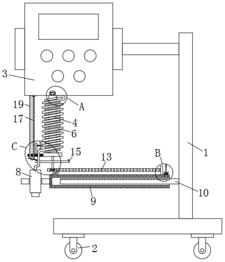
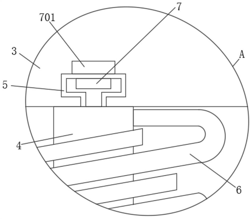
[0031] refer to Figure 1-6 , a non-contact mud layer interface instrument that is convenient to move, including a bracket 1, universal wheels 2 are fixedly installed at the four corners of the lower end of the bracket 1, an interface instrument body 3 is fixedly installed at the left end of the bracket 1, and the interface instrument body The lower end of the 3 is provided with a screw rod 4, and the screw rod 4 is wound with a wire 6, and the lower end of the interface instrument body 3 is provided with a turning groove 5 corresponding to the screw rod 4, and the screw rod 4 is rotationally connected with the interface instrument body 3. Conductive block two 701 is fixedly installed in the lower end of body 3, and conductive block one 7 is fixedly installed on the upper end of screw rod 4 corresponding to conductive block two 701. 7 is fixedly connected, the lower end of the wire 6 is fixedly installed with a detection head 8, the right end of the detection head 8 is fixedly...

Embodiment 2

[0034] refer to Figure 1-6, in this embodiment, it is basically the same as Embodiment 1, and more optimally, a rack 13 is fixedly installed on the upper end of the sleeve 9, a transmission gear 14 is engaged on the left side of the front end of the rack 13, and a transmission gear 14 is fixedly installed on the upper end of the transmission gear 14. Rotating disk 15, the upper end of rotating disk 15 is fixedly installed on the screw rod 4, the lower left side of the screw rod 4 is provided with a whole line board 16, and the wire 6 runs through the right side of the whole line board 16, and the said whole line board 16 is screwed There is a screw 17, the upper end of the screw 17 is rotatably connected with the interface instrument body 3, the lower end of the screw 17 is fixedly equipped with a fixed gear 18, the upper end of the turntable 15 is fixedly equipped with a ring gear 181, and the fixed gear 18 and the ring gear 181 mesh with each other, the screw 17 is rotation...

Embodiment 3

[0037] refer to Figure 1-6 , in this embodiment, it is basically the same as Embodiment 1, and more optimally, the upper side of the whole line board 16 is provided with a loosening plate 24, and the right end of the loosening plate 24 is attached to the wire 6, and the loosening plate 24 is attached to the wire 6. The left end of the plate 24 is fixedly equipped with a spring three 25, and the left end of the spring three 25 is fixedly installed with a riser 26, and the lower end of the riser 26 is fixedly connected to the whole line plate 16;

[0038] During use, under the action of the spring three 25, the anti-loosening plate 24 provided has the effect of squeezing and preventing the loosening of the wire 6 on the upper side of the screw rod 4 when the wire 6 is unwound, thereby preventing the wire 6 from being loosened. In the process of unwinding, there is falling off.

[0039] working principle:

[0040] When the present invention is in use, the positioning rod 11 is...


PUM


Abstract

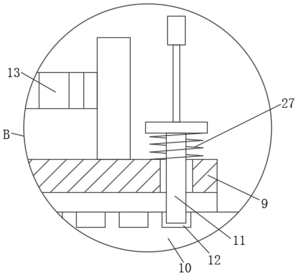
The invention discloses a non-contact mud layer interface instrument convenient to move, which comprises a bracket, universal wheels are fixedly mounted at four corners of the lower end of the bracket, an interface instrument body is fixedly mounted at the left end of the bracket, a screw rod is arranged at the lower end of the interface instrument body, a wire is wound on the screw rod, and a detection head is fixedly mounted at the lower end of the wire. A sleeve is fixedly installed at the right end of the detection head, a fixing rod is inserted into the right end of the sleeve, and the right end of the fixing rod is fixedly installed on the bracket. When the instrument is used, the positioning rod is pulled upwards to slide out of the positioning groove, then the sleeve is pushed to move leftwards on the fixing rod, the sleeve drives the detection head to move leftwards, and therefore the position of the detection head can be conveniently adjusted according to different radii of containers, the detection head can reach the position needing to be detected, the application range is wide, and after adjustment is completed, the positioning rod is loosened and rebounded under the action of a spring 4 and is inserted into the corresponding positioning groove to limit the sleeve.

Description

technical field [0001] The invention relates to the technical field of detection equipment, in particular to a convenient mobile non-contact mud layer interface instrument. Background technique [0002] The sludge interface instrument uses the reliable ultrasonic echo detection principle to detect the distance between the sensor probe and the sludge interface and the distance from the bottom surface, and realizes the real-time monitoring of the sludge thickness change of 0-30 meters and the control of related processes. The sludge interface The instrument optimizes the control of sludge discharge and dosing, prevents the deterioration of effluent, avoids sludge denitrification and decomposition, and optimizes the process control process. [0003] When the existing non-contact mud layer interface instrument is in use, because the radii of the detected mud surface containers are different, when encountering a container with a larger radius, the detection head of the non-contac...

Claims


Application Information

Patent Timeline
Patent Type & Authority Applications(China)
IPC IPC(8): G01F23/296
CPCG01F23/00
Inventor 徐秀丽
Owner 杭州艾科赛德电子科技有限公司
Why Eureka
Eureka Blog
Learn More