Novel device for measuring dynamic coefficient of squeeze film damper

A technology of squeeze oil film damping and oil film damper, which is applied in measuring devices, testing of machine/structural components, instruments, etc., can solve inaccurate measurement of excitation force, low accuracy of evaluation of damping characteristics, and reasonable application of excitation force Poor performance and other problems, easy to evaluate, small and flexible, and avoid complicated test equipment

Pending Publication Date: 2022-01-28
HARBIN INST OF TECH
View PDF0 Cites 0 Cited by
  • Summary
  • Abstract
  • Description
  • Claims
  • Application Information

AI Technical Summary

Problems solved by technology

[0004] In order to solve the problem that the excitation force application method of the existing extrusion oil film damper dynamic coefficient measurement device is not reasonable, the excitation force measuremen

Method used


Image

  • Novel device for measuring dynamic coefficient of squeeze film damper
  • Novel device for measuring dynamic coefficient of squeeze film damper
  • Novel device for measuring dynamic coefficient of squeeze film damper

Examples


specific Embodiment approach 1

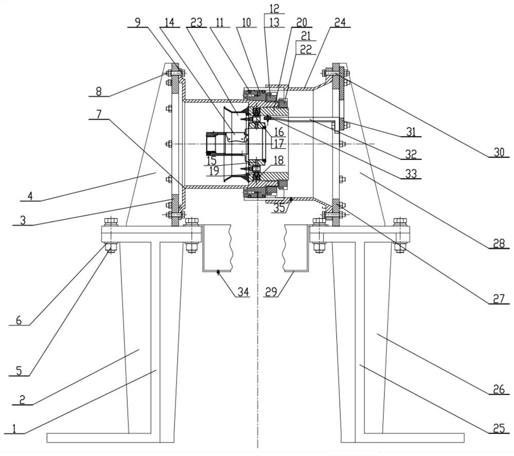
[0042] Specific implementation mode one: refer to Figure 1 to Figure 11 Describe this embodiment. This embodiment provides a novel squeeze film damper dynamic coefficient measuring device, which includes an elastic squirrel cage support assembly, a damping ring support assembly, a weak rigidity elastic squirrel cage support seat 7, an oil film damper Gap adjustment ring 10, two squeeze oil film damper end seal rings 11, No. Force sensor 16, slotted lock nut 18, multiple fixing screws 19, taper sleeve 20, No. 2 stop washer 21, No. 2 lock round nut 22, oil guide ring 23 at the front end of the squirrel cage, outer ring of the damper Bearing seat 24 and displacement sensor assembly;

[0043] The elastic squirrel cage support assembly and the damping ring support assembly are relatively arranged, and the weak stiffness elastic squirrel cage support seat 7 is arranged on the side of the elastic squirrel cage support assembly facing the damping ring support assembly, and one end o...

specific Embodiment approach 2

[0045] Specific implementation mode two: refer to Figure 1 to Figure 11 Describe this embodiment. This embodiment is to further limit the elastic squirrel cage support assembly described in the first specific embodiment. In this embodiment, the elastic squirrel cage support assembly includes a weak rigidity elastic squirrel cage support lower support 1, Multiple weak rigidity elastic squirrel cage support lower support reinforcement ribs 2, weak stiffness elastic squirrel cage support upper support 3, multiple weak stiffness elastic squirrel cage support upper support reinforcement ribs 4, multiple No. 1 full-thread screws A column nut mechanism 5 and a plurality of No. 1 washers 6;

[0046] The lower support 1 of the weak stiffness elastic squirrel cage support is arranged below the upper support 3 of the weak stiffness elastic squirrel cage support, and the lower support 1 of the weak stiffness elastic squirrel cage support passes through a plurality of No. 1 fully threaded...

specific Embodiment approach 3

[0047] Specific implementation mode three: refer to Figure 1 to Figure 11Describe this embodiment. This embodiment is to further limit the damping ring support assembly described in the second specific embodiment. In this embodiment, the damping ring support assembly includes the damper outer ring lower support 25, a plurality of damper Outer ring lower support reinforcement rib 26, damper outer ring upper support 27, multiple damper outer ring upper support reinforcement ribs 28, multiple No. 1 fully threaded stud nut mechanisms and multiple No. 1 washers;

[0048] The lower support 25 of the outer ring of the damper is arranged under the upper support 27 of the outer ring of the damper, and the lower support 25 of the outer ring of the damper is connected with the upper support of the outer ring of the damper through a plurality of No. 1 full-threaded stud nut mechanisms. The seat 27 is tightly connected, and a No. 1 washer is provided between the contact surface between th...


PUM


Abstract

The invention relates to the field of squeeze film dampers, in particular to a novel device for measuring a dynamic coefficient of a squeeze film damper, and aims to solve the problems that an existing squeeze film damper dynamic coefficient measuring device only applies exciting force through power elements such as a driving motor, and the applying mode is poor in reasonability,and the accuracy of damping characteristic evaluation is low. According to the novel device for measuring a dynamic coefficient of a squeeze film damper provided by the invention, a rotary vibration exciter is adopted to excite a weak-rigidity elastic squirrel cage supporting seat, and the excitation state is very close to the working condition of the squeeze film damper in an actual aero-engine and a gas turbine, the identified dynamic coefficient is closer to the actual situation, the vibration reduction performance is easier to evaluate, the rotary vibration exciter is adopted to excite the weak-rigidity elastic squirrel cage supporting seat, the actual excitation state of the rotor is simulated, the problems that the testing device is complex and large in size during actual rotor excitation are solved, and the testing device is small and flexible.

Description

technical field [0001] The invention belongs to the field of squeeze oil film dampers, and in particular relates to a novel squeeze oil film damper dynamic coefficient measuring device. Background technique [0002] Squeeze oil film damper, as a vibration damping device, has a simple structure and excellent vibration damping performance. It plays a major role in the vibration damping of aero-engines and gas turbines, and can significantly improve the reliability of engine operation. [0003] Nowadays, the dynamic coefficient of squeeze film damper is generally used to measure the damper performance and estimate the vibration at the critical speed of the rotor. The dynamic coefficient is identified by obtaining the excitation force and displacement of the damper through the excitation test. The accuracy of the identification mainly depends on The excitation force application method and test principle of the test device are currently applied by driving motors and other power c...

Claims


Application Information

Patent Timeline
IPC IPC(8): G01M13/00
CPCG01M13/00
Inventor 黄延忠张广辉陈亚龙马会防徐科繁国阳龚文杰
Owner HARBIN INST OF TECH
Why Eureka
Try Eureka