Wire structure and forming method thereof
A technology of wires and circuit layers, applied in the field of wire structure and its formation, can solve the problems of not enough to accommodate the conductive material 30, difficult to control the conductive material 30, etc.
Pending Publication Date: 2022-01-28
ADVANCED SEMICON ENG INC
0 Cites 0 Cited by
AI-Extracted Technical Summary
Problems solved by technology
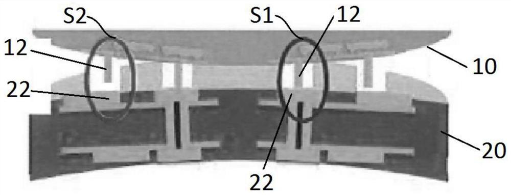
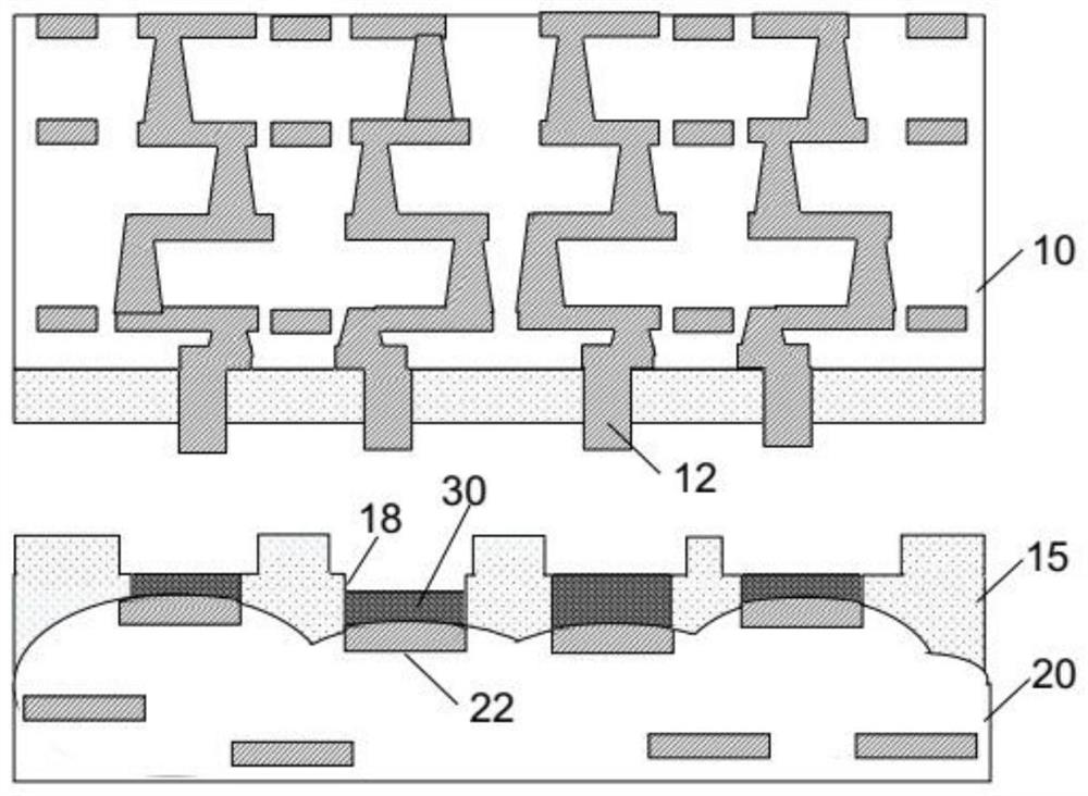
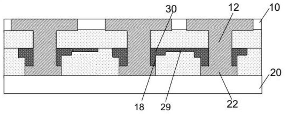
However, since the conductive material 30 is pre-filled in the groove 18, it is difficult to control the amount of the conductive material 30, so when the bump connector 12 of the fan-out layer 10 is engaged with the groove 18, the space o...
Method used
[0043] Referring to FIG. 3A, the conductive glue 250 is not in contact with the dielectric layer 112 of the wiring layer 110, so the conductive glue 250 is spaced apart from the wiring layer 110. The underfill 280 is filled between the circuit layer 110 and the conductive glue 250 , that is, the conductive glue 250 and the circuit layer 110 are separated by the underfill 280 . Utilizing the underfill 280 to fill the gap between the circuit layer 110 and the substrate 210 does not require a groove structure ( FIG. 1B ) to accommodate the conductive material and define the position of the pad, so there will be no conductive material overflowing to cause bridging ( bridge) problem; since there is no need to set the groove structure, the manufacturing process can also be simplified.
[0044] FIG. 4 is a schematic diagram of a wire structure according to another embodiment of the present invention. As shown in FIG. 4 , a protective layer 290 may also be provided. The protective layer 290 covers the lower surface of the circuit layer 110 opposite to the substrate 210 and exposes the bump connectors 230 . In this embodiment, an underfill 280 is disposed between the protective layer 290 and the substrate 210 . The protection layer 290 can protect the bump connector 230 and prevent the bump co...
Abstract
The invention relates to a wire structure and a forming method thereof. The wire structure includes a substrate having a pad at an upper surface of the substrate; and a circuit layer; the circuit layer is located above the substrate, the circuit layer is provided with a convex block connecting piece, and the convex block connecting piece is electrically connected to the bonding pad of the substrate; wherein theconvex connecting piece comprises a first part and a second part located below the first part, and the width of the second part is larger than that of the first part.
Application Domain
Semiconductor/solid-state device detailsSolid-state devices +2
Technology Topic
Electrical connectionStructural engineering +1
Image
Examples
- Experimental program(1)
Example Embodiment
[0035] The following disclosure provides a number of different embodiments or examples of different features for implementing the provided topics. The specific examples of the elements and arrangements will be described below to simplify the present invention. Of course, these are merely examples not intended to limit the invention. For example, in the following description, the first component may include the first component and the second component directly in contact with the second component, and may include additional components between the first component and the second component. The first component and the second component may be in direct contact. Moreover, the present invention can repeat the reference numerals and / or letters in each example. This repetition is for simplicity and clarity, which does not mean the relationship between the various embodiments and / or configurations discussed.
[0036] Figure 2A It is a schematic diagram of a wire structure according to an embodiment of the present invention. like Figure 2A As shown, the line layer 110 is configured with the substrate 210. The line layer 110 is above the substrate 210. The line layer 110 can be a fan-out line layer or a heavy distribution (RDL) layer. A pad 212 is provided at the upper surface of the substrate 210. A bump connector 230 is provided at the lower surface of the line layer 110 opposed to the substrate 210. The bump connector 230 is electrically connected to the pad 212 of the substrate 210 to engage the line layer 110 and the substrate 210.
[0037] Figure 2b It is a schematic diagram of a bump connector of a wire structure according to an embodiment of the present invention. like Figure 2b As shown, the bump connector 230 at the line layer 110 can include a first portion 231 and a second portion 232 connected below the first portion 231. The first portion 231 of the bump connector 230 can be electrically connected to the line layer 110. The width W2 of the second portion 232 of the bump connector 230 is larger than the width W1 in the lateral direction of the first portion 231 in the lateral direction, that is, the second portion 232 of the lower portion of the bump connector 230 has a large width. exist Figure 2b In the illustrated embodiment, the bump connector 230 at the line layer 110 is configured to inverted T shape. The first portion 231 of the bump connector 230 extends vertically in the vertical direction. The second portion 232 of the bump connector 230 extends horizontally in the lateral direction. The first portion 231 has a width W1 in the lateral direction, and the second portion 232 has a width W2 in the lateral direction, and the width W2 of the second portion 232 is larger than the width W1 of the first portion 231. The lower end of the first portion 231 is coupled to the intermediate region of the second portion 232 in the lateral direction to form a rigid block connecting member 230 of the inverted T-shaped.
[0038] Figure 2C A schematic diagram of a bump connector of a wire structure according to another embodiment of the present invention is shown. exist Figure 2C In the illustrated embodiment, the second portion 232 of the bump connector 230 is equally larger than the width W1 in the lateral direction of the first portion 231 in the lateral direction. In this embodiment, the upper surface of the second portion 232 is coupled to the first portion 231. The lower surface of the second portion 232 has a groove structure 235. It should be understood, Figure 2b and Figure 2C The structure of the bump connector 230 shown is merely examples, in other embodiments, the bump connector 230 can be any other structure having a width of the second portion 232 greater than the width of the first portion 231.
[0039] Refer Figure 2AAs shown, the conductive adhesive 250 is located on the pad 212, and the conductive glue 250 also includes a second portion 232 of the bump connector 230. The conductive glue 250 can also cover the lower portion of the first portion 231. The bumps 250 can be bonded by bump connector 230, and then the convex block connecting member 230 and the pad 212 are bonded by the conductive adhesive 250. A single conductive adhesive 250 corresponding to each of the bump connections 230 can be spaced apart from each other. The outer surface of the conductive glue 250 has a surface structure. By designing the bump connector 230 at the line layer 110 to a lower portion having a large width (for example, a T-described T-shaped), the amount and volume of the bump connector 230 can be contacted with adhesive 250.
[0040] In addition, if Figure 2A As shown, the number of pads 212 on the substrate 210 is a plurality of respective and electrically connected to each other with a plurality of bump connections 230. The upper surface of the plurality of pads 212 on the substrate 210 is unpleassed, a high pad 212 (eg, Figure 2A The two pads 212 located in the edge are in contact with the second portion 232 of the respective bump connector 230, and the lower pad 212 (eg, Figure 2A The two pads 212 located in the middle have a spacing (not in contact) with the second portion 232 of the respective bump connector 230. Since the bump connector 230 is stuck with a conductive adhesive 250, the conductive glue 250 fills the interval between the unsucked bump connector 230 and the pad 212, thereby connecting the unsucked bump connector 230 and pads. 212 electrical connection. By using the conductive glue 250 to engage the bump connector 230 and the pad 212, even if the pad 212 on the substrate 210 is different, the electrical connection of each bump connector 230 and the respective pad 212 can be applied. The substrate of the wide line distance from a larger range.
[0041] like Figure 2A As shown, the line layer 110 includes a dielectric layer 112 and a metal line 114 located in the dielectric layer 112. The metal line 114 in the line layer 110 includes a multilayer trace 111 located in the dielectric layer 112 and a through hole 113 of the trace 111 that interconnects different hierarchies. The through hole has a second end 1132 having a small width of the first end 1131 and a large width (width greater than the first end 1131). The first end 1131 of the through hole 113 facing the substrate 210, the second end 1132 of the through hole 113 toward the substrate 210. That is, one end (second end 1132) of the through hole 113 in the line layer 110 is provided as a substrate 210, and the bump connector 230 is a second end 1132 connected to the through hole 113.
[0042] Figure 3A It is a schematic diagram of a wire structure according to another embodiment of the present invention. Figure 3b Yes Figure 3A The zoom schematic of the bump connector and conductive glue. like Figure 3A As shown, the bottom filler 280 can be provided between the line layer 110 and the substrate 210, the bottom filler 280 surrounds the portion of the conductive glue 250 and the bump connector 230 that are not covered by the conductive adhesive 250. The bottom filler 280 is in contact with the substrate 210 and the line layer 110. like Figure 3b As shown, the conductive glue 250 includes a side wall portion 252 covering the side wall of the second portion 232, and the side wall portion 252 is shown Figure 3b The part in the broken line area. The sidewall portion 252 of the conductive glue 250 has a surface structure, and the intersection between the side wall portion 252 of the conductive glue 250 and the bottom filler 280 also has a surface structure. The conductive glue 250 may also include a portion above the upper surface of the second portion 232, which may have a surface structure between the portion and the bottom filler 280.
[0043] refer to Figure 3A As shown, the conductive glue 250 is not in contact with the dielectric layer 112 of the line layer 110, and thus spaces between the conductive glue 250 and the line layer 110. The bottom filler 280 is filled between the line layer 110 and the conductive adhesive 250, i.e., the conductive glue 250 is spaced from the line layer 110 through the bottom filler 280. With the bottom filler 280, the line layer 110 is separated from the substrate 210, and the groove structure can be provided ( Figure 1B To accommodate the conductive material and define the pad position, there is no problem that the bridge (Bridge) is caused by the overflow of the conductive material; the process can be simplified because the groove structure is not required.
[0044] Figure 4 It is a schematic diagram of a wire structure according to another embodiment of the present invention. like Figure 4 As shown, it is also possible to provide a protective layer 290, the protective layer 290 covers the lower surface of the line layer 110 and the substrate 210 and exposes the bump connector 230. In this embodiment, the bottom filler 280 is disposed between the protective layer 290 and the substrate 210. The protective layer 290 can protect the bump connector 230 to avoid the inclinement of the bump connector 230.
[0045] Embodiments of the present invention also provide a method of forming a wire structure. Figure 5 to 12 A plurality of stages of a method of forming a wire structure according to an embodiment of the present invention.
[0046] like Figure 5 and Image 6 As shown, a line layer 110 is formed. like Figure 5 As shown, two layers 111 respectively located at the upper surface of the dielectric layer 112 and the lower surface, respectively, and form a via hole 113 of the two-layer trace 111 vertically interconnected. Then Image 6 As shown, the thickness of the dielectric layer 112 is increased, and continued to stack the more layer trace 111 and the through hole 113 of the interconnected trace 111 in the dielectric layer 112. Finally, a line layer 110 including the trace 111 of the required layer is formed. The multilayer trace 111 and the through hole 113 in the dielectric layer 112 are collectively referred to as the metal line 114 of the line layer 110. In the vertical direction of the multilayer trace 111 of the stacked forming line layer 110, the first end 1131 of the through hole 113 of the line layer 110 ( Image 6 The lower end) The width is less than the second end 1132 ( Image 6 The width of the upper end), the width of the through hole 113 gradually increases from the first end 1131 to the second end 1132. The second end 1132 of the width of the through hole 113 is Image 6 The middle is topward.
[0047] Then Figure 7 As shown, a mask layer 295 having an opening 292 is formed on the line layer 110. The mask layer 295 is above the second end 1132 having a large width of the through hole 113 in the line layer 110. The opening 292 in the mask layer 295 exposes the metal line 114 in the line layer 110.
[0048] like Figure 8 As shown, the conductive material is plated in the opening 292 of the mask layer 295, and the conductive material can be overlate to the opening 292, and the bump connector 230 is electrically connected to the metal line 114 in the line layer 110. The conductive material in the opening 292 forms the first portion 231 extending in the vertical direction, while the conductive material obscraining into the opening 292 forms the second portion 232 extending in the lateral direction. The width of the second portion 232 in the lateral direction is larger than the width of the first portion 231 in the lateral direction such that the bump connector 230 has a T-shaped structure.
[0049] like Figure 9 As shown, the mask layer 295 is removed. The first portion 231 and the second portion 232 of the bump connector 230 are protrude from the dielectric layer 112 of the line layer 110. In another embodiment, some mask layer 295 can also be retained as Figure 4 The protective layer 290 shown in the present can provide protection in the subsequent process 230.
[0050] like Figure 10A Indicated, Figure 9 The resulting structure is inverted such that the second end 1132 having a large width of the through hole 113 faces downward, and the bump connector 230 has an inverted T-shaped structure. The bump connector 230 is at least partially immersed in the material of the conductive glue 250. In some embodiments, at least the second portion 232 of the bump connector 230 is immersed in the material of the conductive glue 250 in the container 259. After removing the bump connector 230 from the material of the conductive glue 250, the bump connector 230 can be admitted to the electro-adhesive 250. By designing the bump connector 230 at the line layer 110 to a lower portion having a large width (for example, a T-described T-shaped), the amount and volume of the bump connector 230 can be contacted with adhesive 250.
[0051] Figure 10B A schematic diagram showing the size of the conductive adhesive 250 dipped on the bump connector 230 before the bonding line layer and the substrate is shown. like Figure 10B As shown in some embodiments, the width W1 of the first portion 231 of the bump connector 230 is in the range of 12 μm to 68 μm. If the width W2 of the second portion 232 of the bump connector 230 is A, the thickness T1 of the second portion 232 is B. Then, the thickness T2 of the conductive adhesive 250 that is viscous at the second portion 232 is approximately A / 2. The width W3 of the conductive adhesive 250 adhesive at the side wall of the second portion 232 is B / 2. Figure 10B Each size is merely examples, in other embodiments, other suitable configurations can also be performed on each dimension.
[0052] like Figure 11A As shown, a substrate 210 having an exposed pad 212 is provided. The number of pads 212 is plural, and the upper surface of the plurality of pads 212 can be unachable. The bump connector 230 is bonded to the pad 212 of the substrate 210 by conductive adhesive 250. After the bump connector 230 is bonded to the substrate 210, the lower pad 212 in the plurality of pads 212 (the two pads 212 in the middle) and a spacing between the corresponding bump connector 230 (not Contact), the conductive glue 250 is filled in the interval. The higher pad 212 (two pads 212 on the edge) contacts the second portion 232 of the respective bump connector 230. Since the bump connector 230 is stuck with a conductive adhesive 250, the conductive glue 250 fills the interval between the unsucked bump connector 230 and the pad 212, thereby connecting the unsucked bump connector 230 and pads. 212 electrical connection. Therefore, by the conductive adhesive 250 to engage the bump connector 230 and the pad 212, even if the pad 212 on the substrate 210 is different, the technical solution provided by the present invention can also ensure each bump connector 230 and the corresponding pad 212. Electrical connection.
[0053] Further, after the bump connector 230 is bonded to the pad 212 of the substrate 210, the bottom filler 280 surrounding the conductive adhesive 250 and the bump connector 230 can also be formed between the line layer 110 and the substrate 210.
[0054] Figure 11B and Figure 11C A schematic diagram showing the size of the conductive adhesive 250 after the bonding line layer 110 and the substrate 210 is shown. like Figure 11B As shown, the conductive glue 250 is deformed after the bonding line layer 110 and the substrate 210, at this time, the width W4 of the conductive glue 250 at the side wall of the second portion 232 is 1 / 4a + 1 / 2b. like Figure 11C As shown, the two pads 212 have a high degree of high difference ΔH, and the height difference ΔH should be in the range of less than A / 2. The height h1 of the bump connector 230 can be in the range of 40 μm to 60 μm. The total height H2 of the bump connector 230 and the pad 212 can be in the range of 40 μm to (60 + 1 / 2a) μm. The pitch (PITCH) P between adjacent bump connections 230 is greater than 2 (C / 2 + a). Figure 11B and Figure 11C Each size is merely examples, in other embodiments, other suitable configurations can also be performed on each dimension.
[0055] like Figure 12As shown, the die 310 joined to the metal line 114 in the line layer 110 is formed over the surface of the back substrate 210 of the line layer 110.Further, the die 310 can also be encapsulated by the molded article 320.
[0056] The above summary features a feature of several embodiments enable those skilled in the art to better understand the various aspects of the disclosure.Those skilled in the art will appreciate that the present invention can be easily designed or changed as the basis for the same purpose and / or implementation of the same purpose as those of the present invention described in the present invention.Those skilled in the art will also appreciate that these equivalent structures do not depart from the spirit and scope of the invention, and various variations, replacements, and changes can be made without departing from the spirit and scope of the invention.
PUM


Description & Claims & Application Information
We can also present the details of the Description, Claims and Application information to help users get a comprehensive understanding of the technical details of the patent, such as background art, summary of invention, brief description of drawings, description of embodiments, and other original content. On the other hand, users can also determine the specific scope of protection of the technology through the list of claims; as well as understand the changes in the life cycle of the technology with the presentation of the patent timeline. Login to view more.