Bendable high-strength cable bridge

A cable tray, high-strength technology, applied to electrical components and other directions, can solve the problems of increasing the difficulty of the bridge splicing work, the unadjustable rotation angle, the offset and shaking of the bridge, etc. Offset shaking effect

Pending Publication Date: 2022-01-28
武雁
View PDF0 Cites 0 Cited by
  • Summary
  • Abstract
  • Description
  • Claims
  • Application Information

AI Technical Summary

Problems solved by technology

[0004] During the installation work of the existing cable trays, if they encounter corners, they usually use fixed corner trays, and the fixed corner trays have non-adjustable rotation angles, and there are few options for cable installation angles, and they are not adjustable; , in the process of bridge splicing, there is no pre-connected structure between the bridges, so in the next fixing work, it is inevitable that there will be offset shaking between adjacent bridges, which increases the difficulty of bridge splicing

Method used


Image

  • Bendable high-strength cable bridge
  • Bendable high-strength cable bridge
  • Bendable high-strength cable bridge

Examples


Embodiment 1

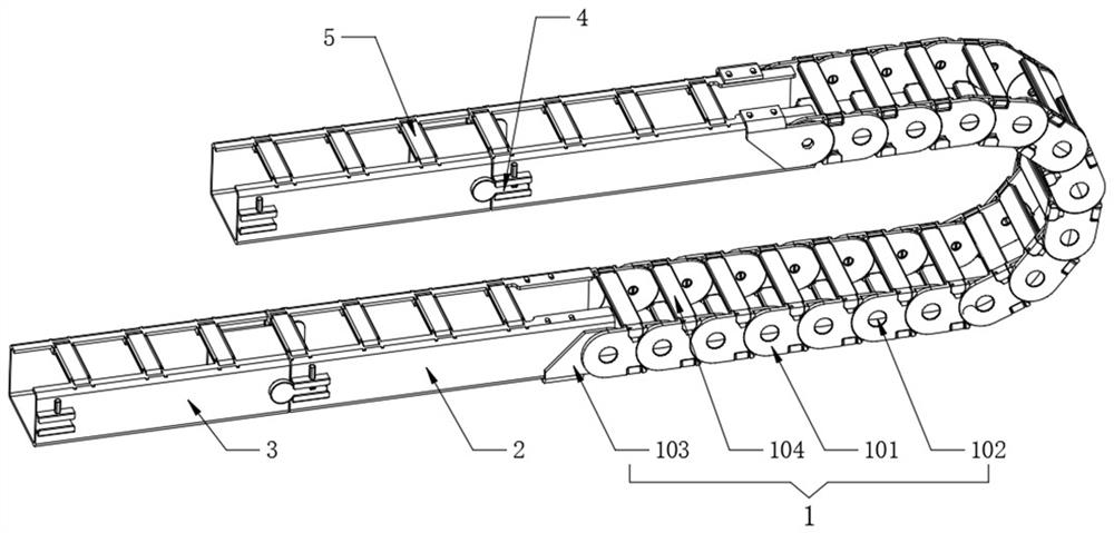
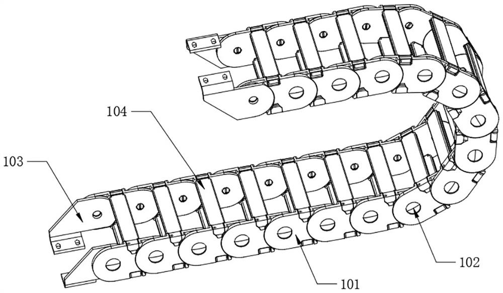
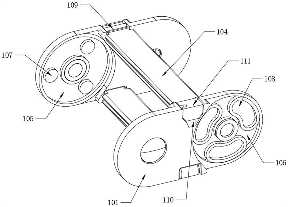
[0038] Refer to attached figure 2 and image 3 , the interior of the transfer bridge assembly 1 is spliced ​​with single-section adapters 101 one by one, and the adjacent single-section adapters 101 are rotated and connected one by one. 104, the two adjacent single-section adapters 101 are rotationally connected by the provided connecting pin 102, the inner walls on both sides of one end of the single-section adapter 101 are fixed with an inner groove 105, and the other side of the single-section adapter 101 Two inner grooves 106 are fixedly formed on the outer walls of both sides of one end, and relative rotation will occur between multiple single-section adapters 101 , and the center of rotation is the corresponding connecting pin 102 .

[0039] Refer to attached image 3, the inner wall of inner groove 1 105 is equidistantly fixed with inner bottom pins 107, the inner wall of inner groove 2 106 is equidistantly fixed with inner arc grooves 108, and the number of inner bo...

Embodiment 2

[0044] Refer to attached Figure 5 One end of the terminating bridge 2 is provided with a screw hole 2 21 corresponding to the screw hole 112, and one end of the splicing bridge 3 is fixedly provided with an interpolation frame 31, and the interpolation frame 31 is movably inserted into one end of the terminating bridge 2, and in the terminating bridge 2 and the splicing bridge 3 are spliced, the interposer frame 31 will be inserted into one end of the terminating bridge 2 to assist the connection between the two.

[0045] Refer to attached Figure 5 The splicing assembly 4 also includes an outer inserting rod 401 and an outer rail frame 403, the outer inserting rod 401 is fixedly arranged on the outer walls of one end of the splicing bridge 3 close to the inner frame 31, and the outer rail frame 403 is fixedly arranged on the other end of the splicing bridge 3 The outer walls on both sides, the outer walls on both sides of the end bridge 2 away from the screw hole two 21 are...

Embodiment 3

[0049] Refer to attached Figure 7 , both sides of the terminating bridge frame 2 and the splicing bridge frame 3 are equidistantly fixed with side center rods, the top protector 5 also includes a top guard plate 501, one end of the top guard plate 501 is fixedly provided with a sleeve 502, and the sleeve 502 is movably sleeved on On the surface of the side center rod, the other end of the top guard plate 501 is fixedly provided with a card tube 503, and the card tube 503 is movably engaged with the side center bar on the other side. The structure is the same. After the splicing of each bridge frame is completed, the top guard plate 501 is covered, and the card tube 503 at the other end of the top guard plate 501 is clamped on the side center rod on the other side, so that the surface of the cable is protected and can block certain The fall of foreign objects.

[0050] Refer to attached Figure 8 , the inner end of the top guard plate 501 is rotatably installed with an inner...


PUM


Abstract

The invention belongs to the technical field, and particularly relates to a bendable high-strength cable bridge which comprises a switching bridge assembly, terminating bridges and splicing bridges, wherein the adjacent splicing bridges are spliced in a contact mode one by one, the splicing bridge at the outermost end is spliced with one terminating bridge through an arranged splicing assembly, the other end of the terminating bridge is spliced with a switching bridge assembly used for changing the direction of a cable, the other terminating bridge is spliced with the other end of the switching bridge assembly, and top protectors are arranged on the upper surfaces of the terminating bridges and the splicing bridges at equal intervals. According to the bendable high-strength cable bridge, a traditional fixed corner bridge can be changed, more multi-angle installation choices can be provided for the cable, the bridge is stable in structure and high in strength, in addition, deviation and shaking between adjacent bridges can be avoided, the working difficulty of bridge splicing is reduced, and finally protection of the surface of the cable is provided.

Description

technical field [0001] The invention belongs to the technical field of cable bridges, in particular to a bendable high-strength cable bridge. Background technique [0002] The cable tray is divided into trough type, tray type, ladder frame type, grid type and other structures, and is composed of brackets, brackets and installation accessories; the bridge frame in the building can be erected independently or laid on various buildings (structures) And the bracket of the pipe gallery should reflect the characteristics of simple structure, beautiful appearance, flexible configuration and convenient maintenance. All parts need to be galvanized and installed on the bridge outside the building. [0003] Problems existing in the prior art: [0004] During the installation work of the existing cable trays, if they encounter corners, they usually use fixed corner trays, and the fixed corner trays have non-adjustable rotation angles, and there are few options for cable installation an...

Claims


Application Information

Patent Timeline
IPC IPC(8): H02G3/04H02G3/06
CPCH02G3/0456H02G3/0406H02G3/06Y02W30/80
Inventor 武雁
Owner 武雁
Why Eureka
Try Eureka