
Wireless optical frequency demodulator with anti-interference structure

A wireless optical and demodulator technology, used in electrical equipment structural parts, cooling/ventilation/heating renovation, electrical equipment enclosures/cabinets/drawers, etc. Normal use, etc.

Inactive Publication Date: 2022-01-28
徐州智谷光频产业研究院有限公司
View PDF0 Cites 0 Cited by
  • Summary
  • Abstract
  • Description
  • Claims
  • Application Information

AI Technical Summary

Problems solved by technology

[0006] In order to solve the above technical problems, the present invention provides a wireless optical frequency demodulator with an anti-interference structure to solve the problem that the dust accumulation of the existing optical frequency demodulator will cause blockage or static electricity to the normal operation of the device. When placed, it is easy to bend the connected wire harness due to bending and affect the normal use of the problem

Method used


Image

  • Wireless optical frequency demodulator with anti-interference structure
  • Wireless optical frequency demodulator with anti-interference structure
  • Wireless optical frequency demodulator with anti-interference structure

Examples


no. 1 example

[0035] as attached figure 1 to attach Figure 10 Shown:

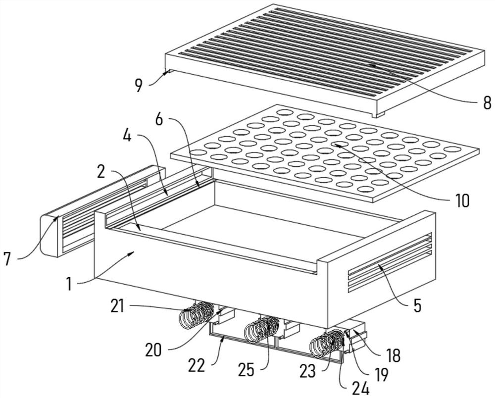
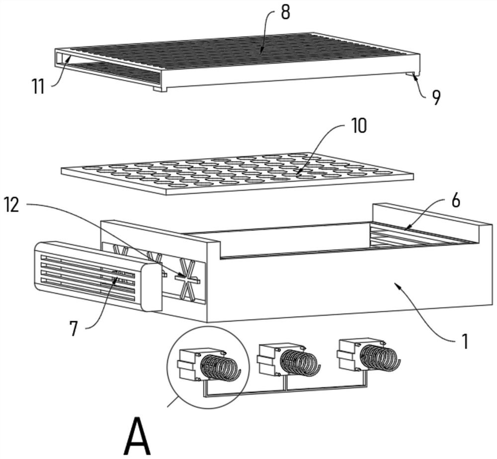
[0036] The present invention provides a wireless optical frequency demodulator with an anti-interference structure, comprising: a housing 1, a guide groove 6 is opened inside the housing 1, the guide groove 6 is used to assemble a guide block 9, the left side of the housing 1 The side is also fixedly connected with a bellows 7, and fans are installed in a linear array inside the bellows 7, and an air outlet 4 is also provided on the left side of the inside of the housing 1. The air outlet 4 matches the air inlet 11, and the bellows 7 matches the air outlet 4. Interconnected with each other, cooling fans 12 are installed in a linear array inside the bellows 7 , and a cover plate 8 is slidably connected to the top of the housing 1 .

[0037] refer to Figure 1-3 , the cover plate 8 is an internal hollow structure, and the top side and the bottom side of the cover plate 8 are provided with heat dissipation grooves in a ...

no. 2 example

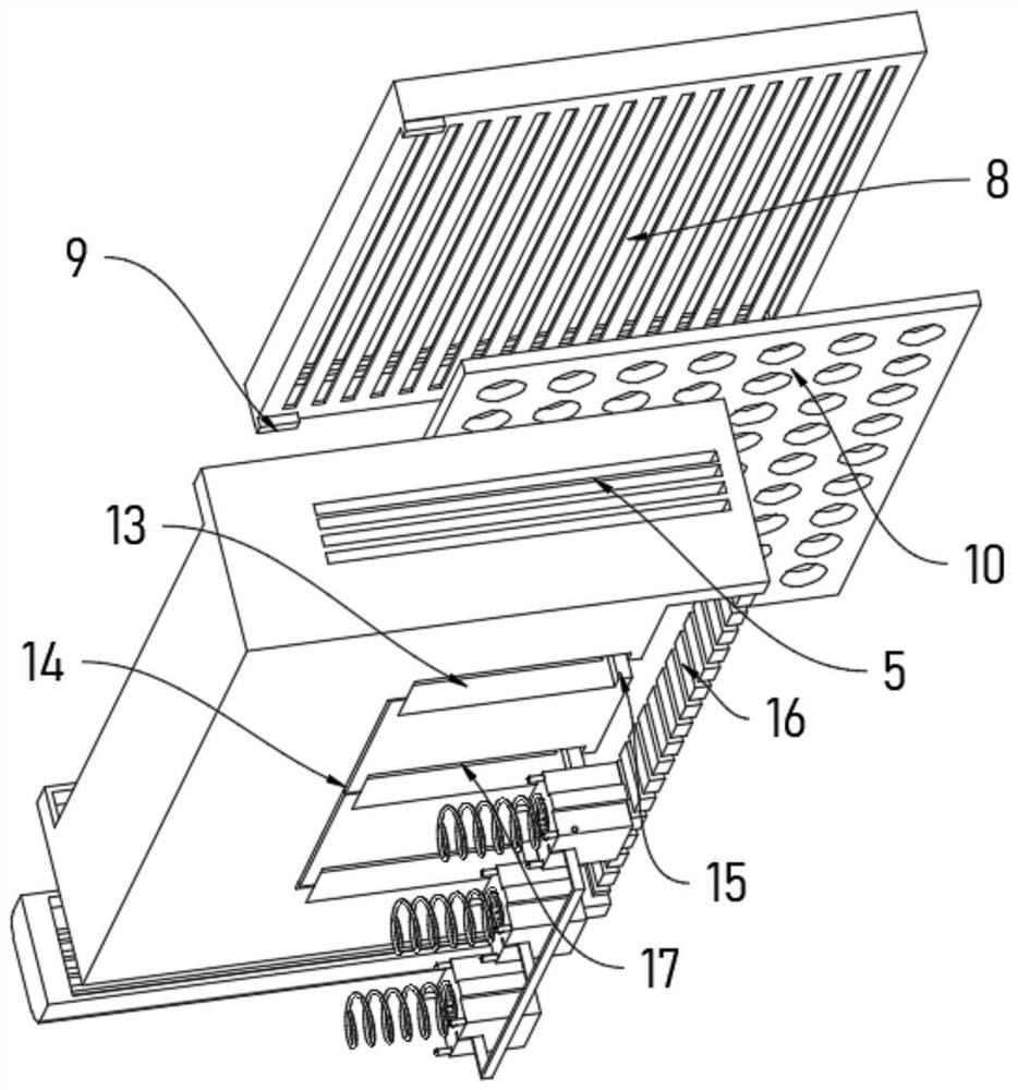
[0043] A wireless optical frequency demodulator with an anti-interference structure provided based on the first embodiment, which uses a housing 1, a connection block 2, an interface 3, a guide groove 6, a cover plate 8, a guide block 9 and a moisture-proof pad 10 The device has realized the efficient protection of the external modules, but in the actual application process, it is still unable to solve the problem that a large amount of dust will accumulate outside the device due to long-term storage and affect the normal operation of the device. In order to solve the above problems, this device is also set There are bellows 7, cooling fans 12, air outlets 4, overflow outlets 5, cover plates 8, guide blocks 9, moisture-proof pads 10 and air inlets 11, refer to Figure 4-7 The rear side of the bottom end surface of the housing 1 is also fixedly connected with a baffle plate 16, the inside of the baffle plate 16 is provided with a square groove in a linear array, the length of th...

no. 3 example

[0046] A wireless optical frequency demodulator with an anti-interference structure provided based on the second embodiment, which is provided by means of a bellows 7, a cooling fan 12, an air outlet 4, an overflow outlet 5, a cover plate 8, a guide block 9, and a moisture-proof pad 10 And the air inlet 11 can solve the problem that there will be a lot of dust on the outside of the device due to long-term storage, which will affect the normal operation of the device, but in practical applications, it is still impossible to efficiently connect the connected wiring harness and complete the anti-interference operation , in order to solve the above problems, the device is also provided with a chute 13, a limit groove 14, a blocking plate 15, a baffle plate 16, an inner groove 17, a mounting block 18, a magnetic column 19, a limiting block 20, and an anti-interference ring 21 , handle 22, magnetic ring 23, return spring 24 and limit plate 25, refer to Figure 4-7 The rear side of t...


PUM


Abstract

The invention provides a wireless optical frequency demodulator with an anti-interference structure, relates to the technical field of optical frequency demodulators, and solves the problems that according to an existing optical frequency demodulator, dust accumulation can cause blockage or electrostatic influence on normal work of a device, and in a humid environment, excessive moisture enters the interior of the device, so short circuit of elements in the device is liable to be caused. The optical frequency demodulator comprises a shell, a guide groove is formed in the shell and used for assembling a guide block, an air bellow is further fixedly connected to the left side of the shell, and fans are installed in the air bellow in a linear array mode; an air outlet is further formed in the left side of the interior of the shell, the air outlet is matched with the air inlet, the air bellow is communicated with the air outlet, a cover plate is slidably connected to the top end of the shell, moisture contained in air flow is filtered through a moisture-proof pad inserted into the inner side of the cover plate, and then the air flow enters the interior of the shell to be subjected to dust removal operation; and then the air is discharged through an air overflow opening formed in the right side of the shell.

Description

technical field [0001] The invention belongs to the technical field of optical frequency demodulators, and more specifically relates to a wireless optical frequency demodulator with an anti-interference structure. Background technique [0002] Optical frequency demodulator, also known as single-port optical transceiver, is a three-piece set of optical fiber transmission equipment developed for special user environments. [0003] The existing optical frequency demodulator still has the following deficiencies: [0004] 1. Most of them are placed on the desktop and placed against the wall, so that the outside of the device will cover a large amount of dust over time, and the accumulation of dust will cause blockage or static electricity to the normal operation of the device, and too much dust in a humid environment Moisture entering the interior of the device can easily cause a short circuit in the original components inside the device. [0005] 2. The terminal is set on the ...

Claims


Application Information

Patent Timeline
Patent Type & Authority Applications(China)
IPC IPC(8): H05K5/02H05K7/20H05K9/00
CPCH05K5/0213H05K5/0247H05K7/20172H05K9/0058H05K9/002H05K5/03
Inventor 夏永文
Owner 徐州智谷光频产业研究院有限公司
Learn More