Novel cable sheath pipe embedded with lighting system and installation method

A lighting system and sheathing technology, applied in the field of cable structures, can solve problems such as interference, achieve the effects of sufficient location space, good manufacturing process performance, and reduce construction difficulty and installation cost

Inactive Publication Date: 2021-04-02
LIUZHOU OVM MASCH CO LTD
View PDF12 Cites 0 Cited by
  • Summary
  • Abstract
  • Description
  • Claims
  • Application Information

AI Technical Summary

Problems solved by technology

[0006] The purpose of the present invention is to solve the problems of the above-mentioned prior art, and propose a new cable sheath tube and installation method for an inlaid lighting system, which solves the problem of the convenience of the sheath control tube process and wiring construction, and the inlaid lights in a narrow space. The problem of interfering with the cable

Method used


Image

  • Novel cable sheath pipe embedded with lighting system and installation method
  • Novel cable sheath pipe embedded with lighting system and installation method
  • Novel cable sheath pipe embedded with lighting system and installation method

Examples


Embodiment 1

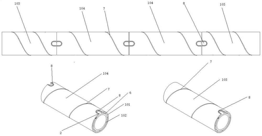
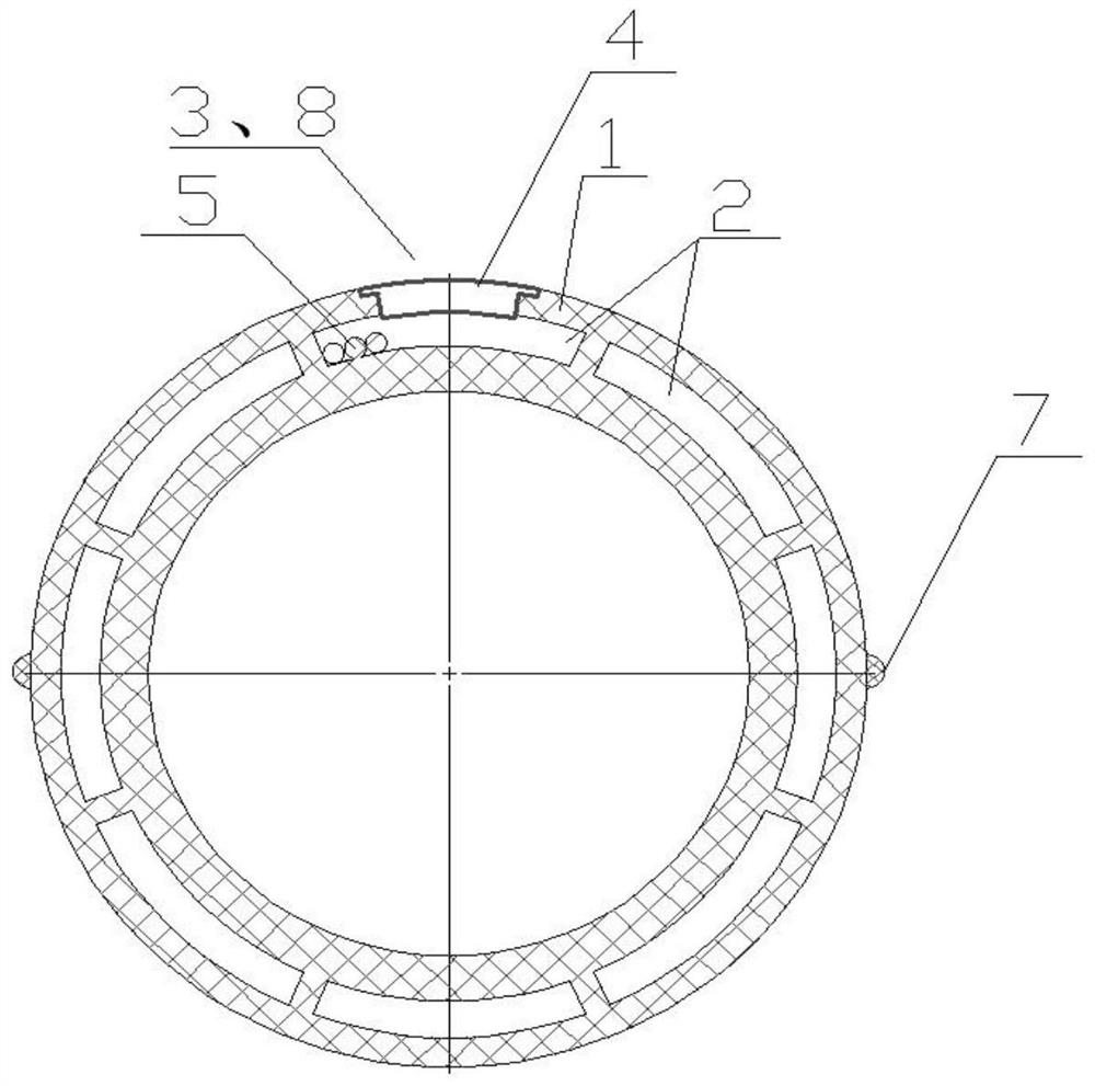
[0034] like figure 1 , Figure 7 As shown, the present invention provides a new type of spiral sheath tube for cables with embedded lighting system. The sheath tube 1 is a double-layer structure sheath tube with an inner layer and an outer layer extruded by a mold. The inner tube layer 101 and the outer layer of the sheath tube 102 are connected by reinforcing ribs 6, and a through hole 2 longitudinally penetrating the sheath tube is provided between the inner layer of the sheath tube 101 and the outer layer 102 of the sheath tube, and the sheath tube includes two The starting and ending end sheath pipe 103 and at least one intermediate section sheathing pipe 104, the middle section sheathing pipe 104 is arranged in series between the two starting and ending end sheathing pipes 103, the starting and ending end sheathing pipe 103 and the middle section sheathing pipe The spliced ​​lamp groove 8 is provided at the abutting end of the sleeve tube 104, the spliced ​​lamp groove 8...

Embodiment 2

[0039] like figure 1 , image 3 and Figure 4 , On the basis of Embodiment 1, the outer surface of the outer layer 101 of the sheath tube is provided with a helix 7 or a pit structure. The outer surface of the outer layer 101 of the sheath tube retains the anti-wind and rain-induced vibration design such as the helix 7 or the pit, which improves the durability of the sheath tube.

Embodiment 3

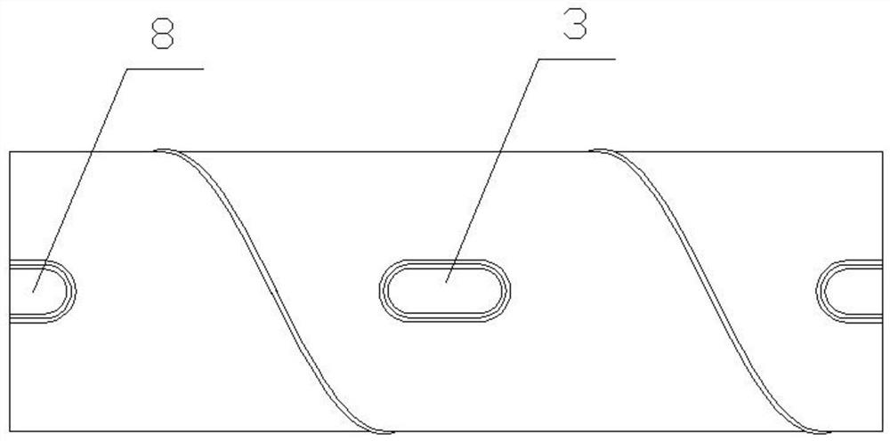
[0041] like figure 2 , Image 6 , On the basis of Embodiment 1, the outer layer of the sheath tube has a lamp groove 3 extending longitudinally, the through hole 2 communicates with the lamp groove 3 , and the lamp groove 3 is used to place the lamp assembly 4 . The lamp groove 3 in this embodiment can be one, and its structure can be the same as the assembled lamp groove 8, or it can be different. When the structure of the lamp groove 3 is different from the assembled lamp groove 8, that is, the sheath tube 1 can At least two or more different lamps are assembled; the lamp groove 3 can also be multiple, and can be combined and processed according to different positions, so that the cable lighting system can achieve more varied lighting effects.


PUM


Abstract

The invention discloses a novel cable sheath pipe embedded with a lighting system and an installation method, the sheath pipe is a double-layer structure sheath pipe with an inner layer and an outer layer, the sheath pipe inner layer and the sheath pipe outer layer are formed by one-time extrusion molding of a die, and the sheath pipe inner layer and the sheath pipe outer layer are connected through a reinforcing rib. A through hole longitudinally penetrating through the sheath pipe is formed between the sheath pipe inner layer and the sheath pipe outer layer, the sheath pipe comprises two start-stop end sheath pipes and at least one middle section sheath pipe, and the middle section sheath pipe is arranged between the two start-stop end sheath pipes in a series connection mode. Splicing type lamp grooves are formed in the ends, abutting against the middle section sheath pipe, of the start-stop end sheath pipes, the splicing type lamp grooves are formed in the two ends of the middle section sheath pipe, the through holes are communicated with the splicing type lamp grooves, the splicing type lamp grooves are used for containing lamp assemblies, and the through holes are used for containing lamp cables. According to the invention, the problems of convenience of a sheath pipe manufacturing process and wiring construction and interference between an embedded lamp and a flat cablein a narrow space are solved.

Description

technical field [0001] The invention relates to the technical field of cable structures, in particular to a novel cable sheath tube and an installation method for an embedded lighting system. Background technique [0002] Bridges play a pivotal role in traffic. With the development of local economies, bridges have become a part of showing local features. With the development of LED technology, lighting design is added to bridge cables, which can reflect the bridge under the night. Its own structural features and modeling features have become a trend in urban lighting. [0003] However, the prior art is applied in the lighting and construction of bridge cables, which are generally considered after the installation of bridge cables is completed, and the construction of high-altitude operations is difficult. The current methods are as follows: one is to use two halves of ring-type hoop lights to hug the cable sheath according to a certain distance, and the cables and control l...

Claims


Application Information

Patent Timeline
Patent Type & Authority Applications(China)
IPC IPC(8): E01D19/16E01D19/00E01D11/04F21V21/00F21V23/00
CPCE01D19/16E01D19/00E01D11/04F21V21/00F21V23/001
Inventor 沈扬波冯文平李华萍陈俊陶文斌吴彦钊陈治良谢锦周俊文闫云友
Owner LIUZHOU OVM MASCH CO LTD
Why Eureka
Try Eureka