Rotary material transfer device applied to numerical control machine tool and production process of rotary material transfer device

A technology of CNC machine tools and transfer devices, which is applied in metal processing and other directions, can solve the problems of increasing occupied area, complex structure, and reducing the efficiency of feeding materials, and achieve the effects of reducing occupied area, simplifying structure, and improving efficiency

Active Publication Date: 2022-02-01
ZHEJIANG JINHUO TECH INDAL
View PDF7 Cites 0 Cited by
  • Summary
  • Abstract
  • Description
  • Claims
  • Application Information

AI Technical Summary

Problems solved by technology

[0003] The purpose of the present invention is to solve the problem that in the existing technology, the existing material transfer device is composed of cylinders in multiple directions, and the workpiece is transported to the outside of the CNC machine tool. The structure is complex and the production cost is high. It increases the occupied area and reduces the efficiency of feeding materials, etc., and proposes a rotating material transfer device and its production process applied to CNC machine tools

Method used


Image

  • Rotary material transfer device applied to numerical control machine tool and production process of rotary material transfer device
  • Rotary material transfer device applied to numerical control machine tool and production process of rotary material transfer device
  • Rotary material transfer device applied to numerical control machine tool and production process of rotary material transfer device

Examples


Embodiment Construction

[0024] Next, we will further describe a rotary material transfer device and its production process for CNC machine tools according to the present invention in conjunction with the accompanying drawings.

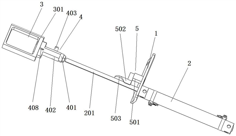
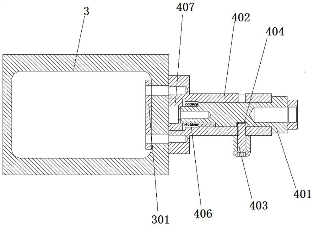
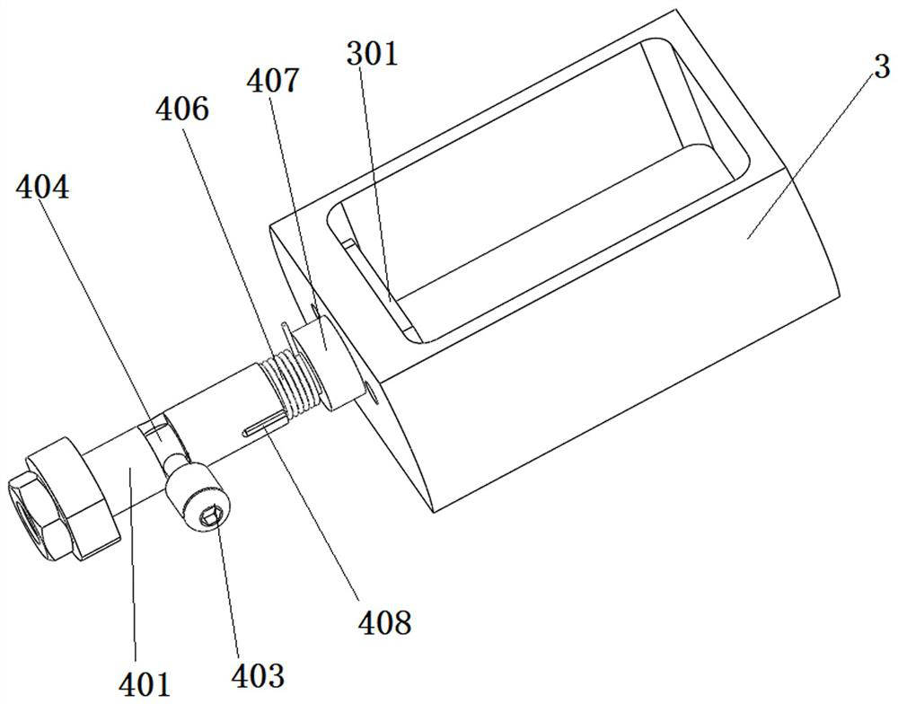
[0025] See attached figure 1 As shown, in this embodiment, a rotary material transfer device applied to CNC machine tools includes a base 1, a drive cylinder 2 mounted on the base 1 by screws, and a hopper 3 connected to the drive cylinder 2; its features are also It includes a rotating mechanism 4 installed between the drive cylinder 2 and the hopper 3 to drive the hopper 3 to rotate; the base 1 is also equipped with a rotating guide assembly 5 that guides the rotating mechanism 4; through the setting of the rotating mechanism 4, Utilize the rotating mechanism 4 to drive the receiving hopper 3 to rotate and reset, thereby improving the efficiency of material receiving, and also reducing the area occupied, and reducing the cost of use; through the setting of the rotating guid...


PUM


Abstract

The invention discloses a rotary material transfer device applied to a numerical control machine tool. The rotary material transfer device comprises a base, a driving cylinder installed on the base and a material receiving hopper connected with the driving air cylinder, and is characterized by further comprising a rotating mechanism which is mounted between the driving cylinder and the receiving hopper and drives the receiving hopper to rotate. The base is further provided with a rotation guide assembly playing a role in guiding the rotating mechanism. Through the arrangement of the rotating mechanism, the receiving hopper is driven by the rotating mechanism to rotate and reset, so that the receiving efficiency is improved, meanwhile, the occupied area is reduced, and the use and production are reduced; through the arrangement of the rotation guide assembly, the rotation guide assembly is used for guiding rotation and resetting of the rotating mechanism, so that the structure is simplified, and the production cost is reduced; and through the arrangement of a torsion spring in the rotating mechanism, the elasticity of the torsion spring drives the rotating mechanism to reset, so that the situation that the receiving hopper is not reset in place, and normal receiving is affected is prevented.

Description

technical field [0001] The invention relates to the technical field of CNC machine tool accessories, in particular to a rotary material transfer device applied to a CNC machine tool and a production process thereof. Background technique [0002] CNC machine tool is the abbreviation of digital control machine tool. It is an automatic machine tool equipped with a program control system. According to the shape and size required by the drawing, the parts are automatically processed. The workpiece processed by the machine tool is transported from the CNC machine tool to the outside of the CNC machine tool, but in the existing technology, the existing material transfer device is composed of cylinders in multiple directions to transport the workpiece to the outside of the CNC machine tool, and its structure is complicated. The production cost is high, and the combination of multiple cylinders also increases the occupied area and reduces the feeding efficiency. For this reason, a r...

Claims


Application Information

Patent Timeline
Patent Type & Authority Applications(China)
IPC IPC(8): B23Q7/00B23Q7/10
CPCB23Q7/00B23Q7/10
Inventor 陈永马佳羊昱乘洪学斌叶智伟赵鹏程朱铭
Owner ZHEJIANG JINHUO TECH INDAL
Why Eureka
Try Eureka