
Mold structure for forming and processing bionic bait

A technology for forming and processing bionic fishing bait, which is applied in the field of mold structures for bionic fishing lure forming and processing, can solve the problems of not having multiple adjustment structures, no auxiliary demolding structure, reducing the working efficiency of the mold, etc. Easy to operate and easy to use repeatedly

Pending Publication Date: 2022-02-01
安徽宏飞钓具有限公司
View PDF1 Cites 1 Cited by
  • Summary
  • Abstract
  • Description
  • Claims
  • Application Information

AI Technical Summary

Problems solved by technology

[0004] The existing mold structure for bionic bait molding processing has certain disadvantages in the process of use. The traditional mold structure for bionic bait molding processing does not have an auxiliary demoulding structure, and the mold structure for bionic bait molding processing can process multiple groups of materials at one time. When the mold structure for bionic bait molding processing is used for material retrieving operations, it is impossible to complete the retrieving operation of multiple pieces of bionic bait at one time, which reduces the working efficiency of the mold; secondly, the traditional mold structure for bionic bait molding processing does not have multiple adjustment structures. The corresponding adjustment operation cannot be performed according to the type of bionic bait, which reduces the flexibility of the mold structure for bionic bait molding and processing, and brings certain adverse effects to users

Method used


Image

  • Mold structure for forming and processing bionic bait
  • Mold structure for forming and processing bionic bait
  • Mold structure for forming and processing bionic bait

Examples


Embodiment Construction

[0027] In order to further explain the technical means and effects of the present invention to achieve the intended purpose of the invention, the specific implementation, structure, features and effects of the present invention will be described in detail below in conjunction with the accompanying drawings and preferred embodiments.

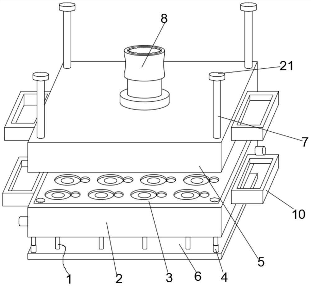
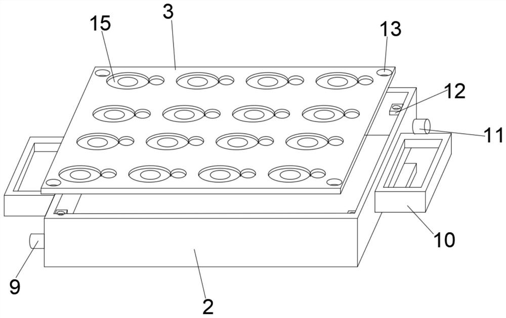
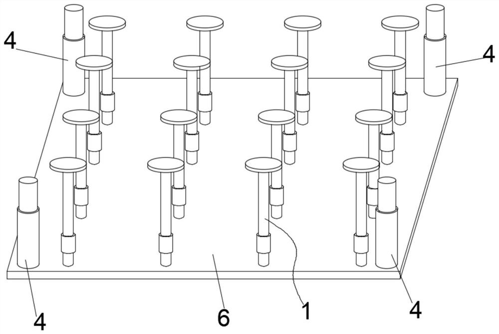
[0028] Such as Figure 1-4 As shown, a mold structure for bionic bait molding processing includes a lower mold body 2 and an upper mold body 5, and the upper mold body 5 is spliced ​​and installed on the outer surface of the upper end of the lower mold body 2, between the lower mold body 2 and the upper mold body 5 There are four sets of positioning guide rods 7 for positioning, the bottom of the lower mold body 2 is provided with a support base plate 6, and several sets of ejector rods for ejecting materials are arranged between the lower mold body 2 and the support base plate 6 1. The lower mold body 2 and the support base plate 6 are elastical...


PUM


Abstract

The invention discloses a mold structure for forming and processing bionic bait. The mold structure comprises a lower mold body and an upper mold body, the upper mold body is mounted on the outer surface of the upper end of the lower mold body in a spliced mode, four sets of positioning guide rods used for positioning are connected between the lower mold body and the upper mold body in a sleeved mode, and a supporting bottom plate is arranged at the bottom of the lower mold body; a plurality of sets of ejector rods used for ejecting materials are arranged between the lower mold body and the supporting bottom plate, and the lower mold body and the supporting bottom plate are elastically connected through four sets of spring ejector rods. By means of the arrangement of the supporting bottom plate, multiple sets of ejector rods can be installed at the same time, discharging operation of multiple sets of shaping grooves can be conveniently carried out, meanwhile, by means of the arrangement of spring ejector rods, elastic reset operation can be carried out between the lower mold body and the supporting bottom plate after the lower mold body is pressed downwards, the lower mold body can be conveniently and repeatedly used, by means of the ejector rods and the supporting bottom plate, the mold for bionic bait forming and processing can carry out lifting type material jacking operation, and material taking operation is more convenient and faster.

Description

technical field [0001] The invention belongs to the technical field of bionic fishing bait processing, and more specifically relates to a mold structure for forming and processing bionic fishing bait. Background technique [0002] The mold structure for bionic bait molding processing is a structure used in the bionic bait molding process to perform mold setting operations on bionic baits made of plastic materials. Using this mold structure, multiple groups of bionic baits can be processed at one time. [0003] Patent No. CN113229231A discloses a kind of intelligent bionic bait processing equipment and bionic bait processing method, which belongs to the field of bionic bait forming technology, including a workbench, the middle of the top of the workbench is fixedly connected with a mounting frame, and the top of the mounting frame is A hot-melt mechanism is fixedly connected in the middle, hydraulic rods are fixedly connected to both sides of the bottom end of the mounting fr...

Claims


Application Information

Patent Timeline
IPC IPC(8): B29C45/17B29C45/26B29C45/40
CPCB29C45/2606B29C45/4005B29C45/1756
Inventor 马宏孙振孔银强
Owner 安徽宏飞钓具有限公司
Learn More