

Method of diagnosing valve, diagnosis module, and valve
An electric actuator, changing curve technology, applied in the direction of valve operation/release device, valve detail, diaphragm valve, etc., can solve problems such as inability to determine the stroke and the inability of the sensor to detect reliably
- Summary
- Abstract
- Description
- Claims
- Application Information
AI Technical Summary
Problems solved by technology
Method used
Image

Examples
Embodiment Construction
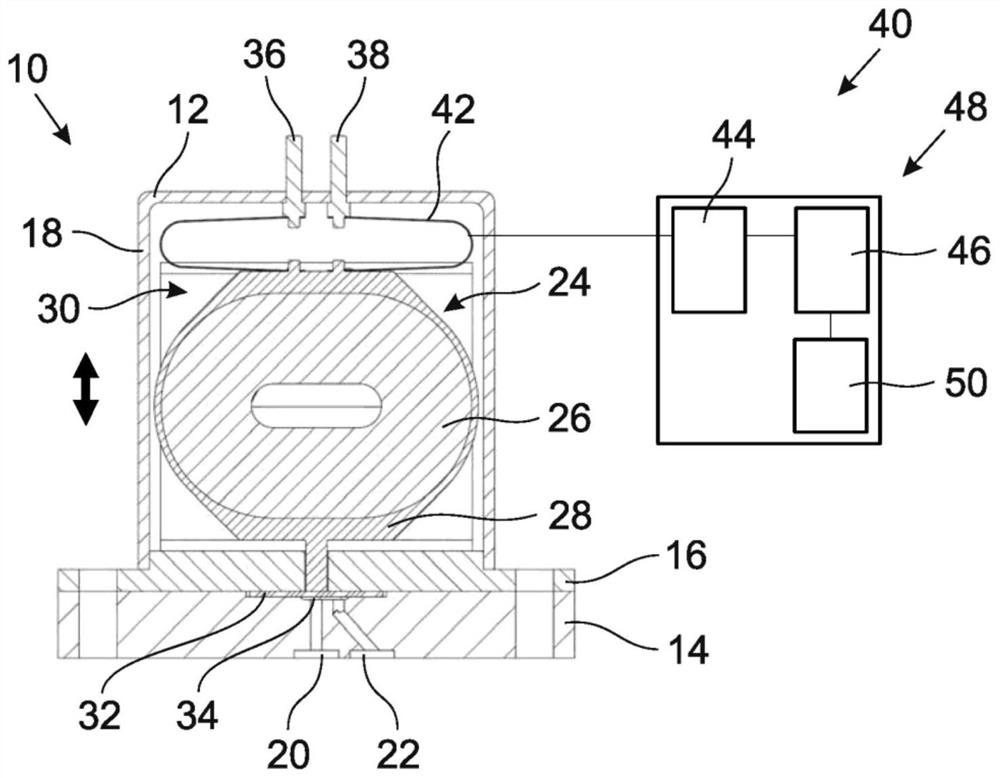
[0054] figure 1 A valve 10 is shown in FIG. 2 , which has a housing 12 which, for example, consists of a plurality of housing parts 14 , 16 , 18 .
[0055] Two fluid connections 20 , 22 are formed on the housing 12 , in particular the first housing part 14 , via which fluid can flow through the valve 10 and which fluid is processed accordingly by the valve 10 .
[0056] An electric actuator 24 is provided for controlling the fluid to be treated, which comprises a coil 26 designed as an air-core coil and an adjustment element 28 coupled to the coil 26 . Furthermore, the electric actuator 24 has a magnet arrangement 30 which is figure 1 are shown schematically only.
[0057] The magnet arrangement 30 generates a magnetic field in which the coil 26 is movably arranged such that the coil 26 moves within the magnetic field generated by the magnet arrangement 30 as soon as the coil 26 is energized, ie is charged with a current. The movement of the coil 26 is transmitted to the mo...
PUM
 Abstract
Description
Claims
Application Information