Component aerodynamic load correction method based on wind tunnel test

An aerodynamic load and wind tunnel test technology, applied in the field of aerodynamics, can solve the problems of complex test, poor calculation result accuracy, high cost, and achieve the effect of reasonable calculation result and shortened design period.

Pending Publication Date: 2022-02-01
江西洪都航空工业股份有限公司
View PDF0 Cites 2 Cited by
  • Summary
  • Abstract
  • Description
  • Claims
  • Application Information

AI Technical Summary

Problems solved by technology

[0002] The aerodynamic load of aircraft components is the main input of the structural strength design, which has a great influence on the structural strength design of the aircraft. The methods for obtaining the aerodynamic load of aircraft components are divided into test and calculation. The test is complicated, the cycle is long and the cost is high. The test method is not suitable in the initial design stage. , while the CFD calculation is simple, the cycle is short and the cost is low, but the accuracy of the calculation results is relatively poor compared with the test; the force measurement wind tunnel test is generally carried out in the initial design stage of the aircraft, and the total aerodynamic load of the aircraft obtained from the force measurement wind tunnel test can be Using CFD to calculate the component load, combined with the results of the force measurement wind tunnel test, develop a component aerodynamic load correction method based on the wind tunnel test, which improves the accuracy of the calculation results

Method used


Image

  • Component aerodynamic load correction method based on wind tunnel test
  • Component aerodynamic load correction method based on wind tunnel test
  • Component aerodynamic load correction method based on wind tunnel test

Examples


Embodiment Construction

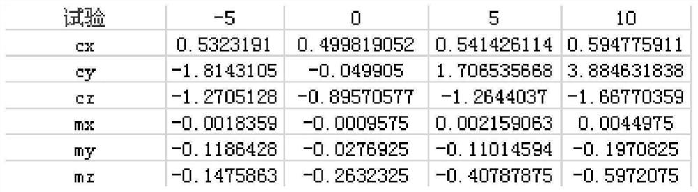
[0031] 1) Write the dynamometric wind tunnel test task book, formulate the content of the wind tunnel test, conduct the dynamometric wind tunnel test, sort out the dynamometric wind tunnel test results, and obtain the total aerodynamic load of the aircraft, see the attached figure 1 ;

[0032] 2) Divide each part of the projectile body and mark it with i, i=1, 2, ... n;

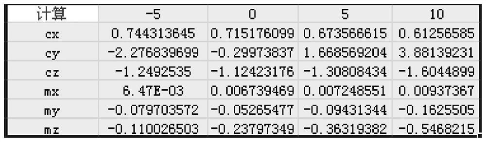
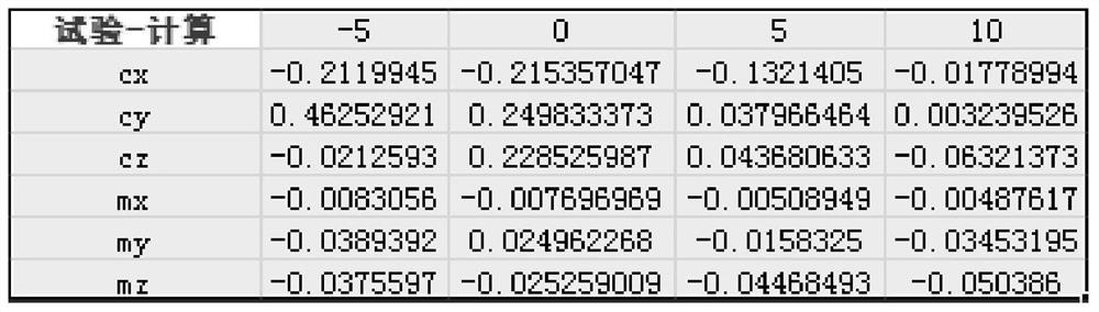
[0033] 3) Calculate the aerodynamic load A' of each component for the fluid 1 , A' 2 ,...,A' n , it is necessary to divide the parts of the missile body. The division method should follow that the parts with large changes in aerodynamic load should be densely divided, and the parts with small changes in aerodynamic load should be divided sparsely. The division method of the parts of the projectile body is as follows:

[0034] For example, the bullet is divided into one section; the section from the bullethead to the front edge of the wing, the section from the front edge of the wing to the rear edge of the...


PUM


Abstract

The invention belongs to the technical field of aerodynamics, and discloses a component aerodynamic load correction method based on wind tunnel test. The method comprises the following steps of: 1, obtaining a total aerodynamic load test value A of a projectile according to a force measurement wind tunnel test; 2, calculating the fluid number of the projectile to obtain the total aerodynamic load calculation value A' of the projectile and the aerodynamic load calculation values A'1, A'2,..., A'n of all components; 3, calculating the difference Delta between the total aerodynamic load test value and the calculation value of the projectile; 4, respectively calculating a proportionality coefficient ki of the aerodynamic load calculation value of each component and the total aerodynamic load calculation value of the projectile, wherein i = 1, 2,... n; 5, according to the difference between the total aerodynamic load test value and the total aerodynamic load calculation value of the projectile and the proportionality coefficient ki between the aerodynamic load calculation value of each component and the total aerodynamic load calculation value of the projectile, calculating the aerodynamic load correction Deltai of each component; and 6, based on the aerodynamic load correction amount of each component and the aerodynamic load calculation value of each component, obtaining an aerodynamic load correction value of each component.

Description

technical field [0001] The invention belongs to the technical field of aerodynamics, and relates to a component aerodynamic load correction method based on a wind tunnel test. Background technique [0002] The aerodynamic load of aircraft components is the main input of the structural strength design, which has a great influence on the structural strength design of the aircraft. The methods for obtaining the aerodynamic load of aircraft components are divided into test and calculation. The test is complicated, the cycle is long and the cost is high. The test method is not suitable in the initial design stage. , while the CFD calculation is simple, the cycle is short and the cost is low, but the accuracy of the calculation results is relatively poor compared with the test; the force measurement wind tunnel test is generally carried out in the initial design stage of the aircraft, and the total aerodynamic load of the aircraft obtained from the force measurement wind tunnel tes...

Claims


Application Information

Patent Timeline
Patent Type & Authority Applications(China)
IPC IPC(8): G01M9/06
CPCG01M9/06
Inventor 张辉周晓华刘涛赵小勇朱鹏罗剑波李娟娟栗莉魏树孝郝传海章仕耀
Owner 江西洪都航空工业股份有限公司
Why Eureka
Try Eureka