Tree irrigation device for landscaping

A watering device and landscaping technology, applied in the direction of watering devices, spraying devices, fertilization devices, etc., can solve the problems of wasting water resources, difficult to move equipment, etc., and achieve the effect of reducing workload

Pending Publication Date: 2022-02-08
曹赓应
View PDF0 Cites 0 Cited by
  • Summary
  • Abstract
  • Description
  • Claims
  • Application Information

AI Technical Summary

Problems solved by technology

[0003] In order to overcome the shortcomings of existing watering devices that not only waste water resources, but also that the equipment is difficult to move, the technical problem to be solved is to provide a tree watering device for landscaping that can save water resources and be easy to move

Method used


Image

  • Tree irrigation device for landscaping
  • Tree irrigation device for landscaping
  • Tree irrigation device for landscaping

Examples


Embodiment 1

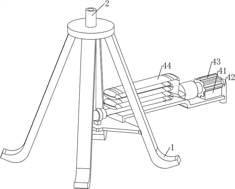
[0026] A tree watering device for landscaping, such as Figure 1-3 As shown, it includes a mounting frame 1, a water injection pipe 2, a nozzle 3, a water inlet mechanism 4 and a swing mechanism 5. The installation frame 1 is provided with a water injection pipe 2 in the middle, and the top of the water injection pipe 2 is rotatably connected to the nozzle 3. The bottom of the mounting frame 1 A water inlet mechanism 4 is arranged between the right side and the water injection pipe 2 , and a swing mechanism 5 is arranged between the installation frame 1 and the nozzle 3 .

[0027] The water inlet mechanism 4 includes a first support plate 41, a water inlet pipe 42, a water pump 43 and a hose 44. The right side of the lower part of the mounting frame 1 is provided with a first support plate 41, and the top of the first support plate 41 is provided with a water pump 43. The water pump 43 A water inlet pipe 42 is arranged on the right side, a hose 44 is arranged between the left ...

Embodiment 2

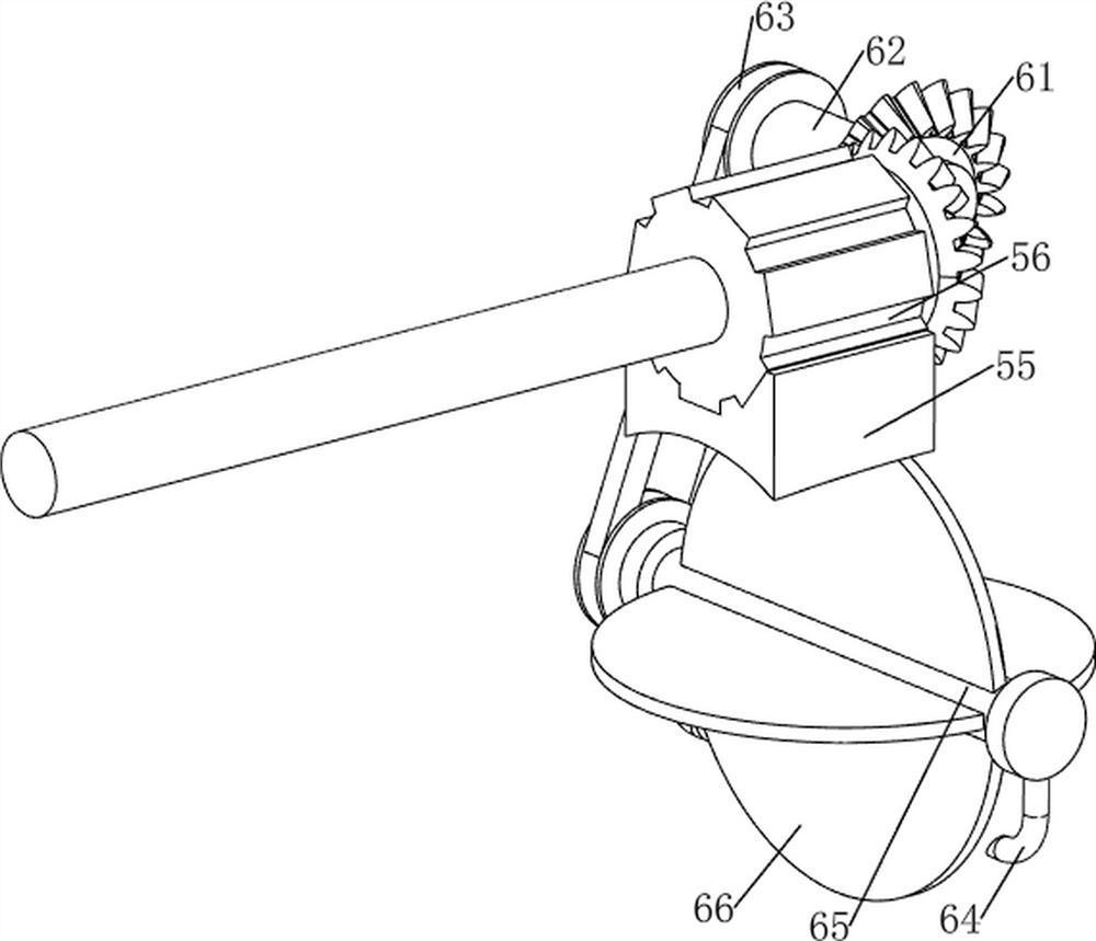
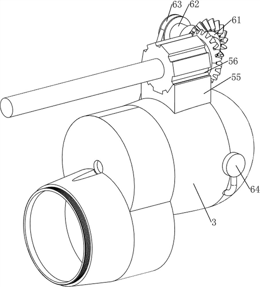
[0031] On the basis of Example 1, such as Figure 4-9 As shown, a rotating mechanism 6 is also included. The rotating mechanism 6 includes a bevel gear set 61, a third rotating shaft 62, a transmission assembly 63, a second support frame 64, a fourth rotating shaft 65 and a movable plate 66. The right rear side of the spray head 3 rotates. A third rotating shaft 62 is connected in the same way, and a bevel gear set 61 is arranged between the front side of the third rotating shaft 62 and the right side of the output shaft of the servo motor 56. The front and rear sides of the right part of the nozzle 3 are connected with a second support frame 64, and the second support A fourth rotating shaft 65 is rotatably connected between the frames 64, and a movable plate 66 is uniformly arranged on the fourth rotating shaft 65, and the movable plate 66 is located in the nozzle 3, and a rear side of the fourth rotating shaft 65 and the third rotating shaft 62 are provided with a Transfer ...


PUM


Abstract

The invention relates to an irrigation device, in particular to a tree irrigation device for landscaping. The technical problem to be solved is to provide the tree irrigation device for landscaping, which can save water resources and is convenient to move. According to the technical scheme, the tree irrigation device for landscaping comprises a mounting frame, a water injection pipe, a spray head, a water inlet mechanism and a swing mechanism, the water injection pipe is arranged in the middle of the mounting frame, the top of the water injection pipe is rotationally connected with the spray head, the water inlet mechanism is arranged between one side of the mounting frame and the water injection pipe, and the swing mechanism is arranged between the mounting frame and the spray head. Through cooperation of the water inlet mechanism and the swing mechanism, the effect of uniformly spraying water to irrigate trees can be achieved, the water spraying position does not need to be manually adjusted, and the workload of people can be reduced.

Description

technical field [0001] The invention relates to a watering device, in particular to a tree watering device for landscaping. Background technique [0002] In urban landscaping, more and more large trees are transplanted, and large trees need a lot of water to survive. Most of the existing waterers can only water the trees in large quantities. This watering method consumes a lot of water. , not only wasting water resources, but also the equipment is difficult to move. Therefore develop a kind of tree watering device that can realize water saving and be convenient to move now for landscaping. Contents of the invention [0003] In order to overcome the shortcomings of the existing watering devices, which not only waste water resources, but also are difficult to move, the technical problem to be solved is to provide a tree watering device for landscaping that can save water resources and be easy to move. [0004] The technical scheme of the present invention is: a tree wate...

Claims


Application Information

Patent Timeline
IPC IPC(8): A01G25/09A01C23/04B05B3/14B05B15/25
CPCA01G25/09A01C23/042A01C23/047B05B3/14B05B15/25
Inventor 曹赓应
Owner 曹赓应
Why Eureka
Try Eureka