Sealing gasket manufacturing tool
A technology for making tools and gaskets, which is applied in the field of gasket making tools, can solve the problems of affecting the sealing performance of sealing rubber ring gaskets, increasing equipment moisture, and increasing material loss rate, etc., to achieve efficient and fast cutting, reduce loss, and simple operation Effect
- Summary
- Abstract
- Description
- Claims
- Application Information
AI Technical Summary
Problems solved by technology
Method used
Image
Examples
Embodiment 1
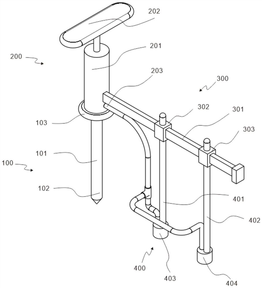
[0029] refer to figure 1 , is the first embodiment of the present invention, which provides a gasket manufacturing tool, the gasket manufacturing tool includes a fixing assembly 100 , a pressing assembly 200 , a measuring assembly 300 and a scribing assembly 400 .
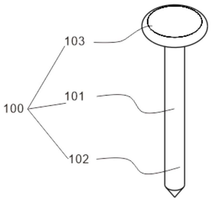
[0030] Specifically, the fixing assembly 100 includes a fixing column 101, and also includes a fixing tip 102, which is arranged at the bottom of the fixing column 101, and also includes a fixing handle 103, which is arranged at the top of the fixing column 101. When in use, the fixing tip 102 is stuck on the surface of the rubber , to fix the gasket making tool to prevent device displacement during cutting.
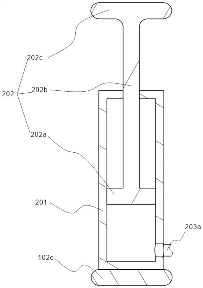
[0031] Specifically, the compression assembly 200 includes a compression tube 201 disposed on the top of the fixed handle 103, a compression piston 202 disposed inside the compression tube 201, and a compression air pipe part 203 disposed on the bottom of the compression tube 201. On one side, when the compr...
Embodiment 2
[0036] refer to figure 1 figure 2 and image 3 , is the second embodiment of the present invention, which is based on the previous embodiment.
[0037] Specifically, the bottom of the compression tube 201 is fixedly connected to the fixed handle 103, and the side of the bottom of the compression tube 201 is provided with an air outlet, and the gas inside the compression tube 201 will be transferred through the air outlet when it is under pressure.
[0038] Specifically, the compressed air pipe part 203 includes an air inlet pipe 203a, and the air inlet pipe 203a is connected with an air outlet hole on the bottom side of the compression pipe 201, and the gas inside the compression pipe 201 will move to the air inlet pipe 203a through the air outlet hole when it is under pressure. Inside.
[0039] Specifically, the compressed air pipe part 203 also includes a No. 1 air outlet pipe 203b, a No. 2 air outlet pipe 203c and a three-way pipe 203d. The gas inside the tight pipe 20...
Embodiment 3
[0043] refer to figure 1 Figure 4 and Figure 5 , is the third embodiment of the present invention, which is based on the first two embodiments.
[0044] Specifically, the No. 1 locking pin 302 is sleeved on the outside of the scale rod 301, including the No. 1 casing 302a and the No. 1 pin 302b. The top of the No. 1 casing 302a is provided with a screw hole, and the No. 1 pin 302b and the No. 1 casing 302a threaded connection, the No. 2 locking pin 303 is sleeved on the outside of the scale rod 301, including the No. 2 casing 303a and the No. 2 pin 303b, and the top of the No. The shell 303a is threadedly connected, and the sleeve shell is sleeved on the outside of the scale bar 301. The pin can move the sleeve shell when it is loose through the threaded hole on the top of the sleeve shell, and fix the sleeve shell when it is tight.
[0045] Specifically, the top of the No. 1 outrigger 401 is welded to the bottom of the No. 1 locking pin 302, the top of the No. 2 outrigge...
PUM
 Abstract
Description
Claims
Application Information
 - R&D
- Intellectual Property
- Life Sciences
- Materials
- Tech Scout
- Unparalleled Data Quality
- Higher Quality Content
- 60% Fewer Hallucinations
Browse by: Latest US Patents, China's latest patents, Technical Efficacy Thesaurus, Application Domain, Technology Topic, Popular Technical Reports.
© 2025 PatSnap. All rights reserved.Legal|Privacy policy|Modern Slavery Act Transparency Statement|Sitemap|About US| Contact US: help@patsnap.com


