Steel mold for prefabricated concrete lintel of distribution box, and assembly structure and construction method of steel mold
A technology for concrete and distribution boxes, which is applied in the direction of manufacturing tools, mold fixtures, molds, etc., can solve problems such as damage to masonry, and achieve the effects of ensuring construction quality, good appearance, and improving production efficiency
- Summary
- Abstract
- Description
- Claims
- Application Information
AI Technical Summary
Problems solved by technology
Method used
Image

Examples
Embodiment 1
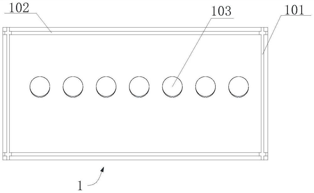
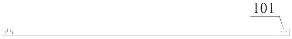
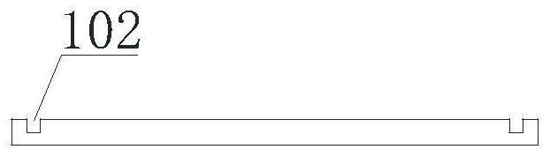
[0038] see Figure 1 to Figure 11 , the present invention is a prefabricated distribution box concrete lintel steel mold, which includes a bottom mold 1, a short side mold 2, a long side mold 3, a top mold 4, a plug core 5 and a bolt 6, the bottom mold 1, the short The side molds 2 , the long side molds 3 and the top mold 4 are all made of metal plates including but not limited to, and are generally made of steel plates. The bottom mold 1 is rectangular, and the corresponding two short sides and the inner sides of the two long sides on the top are respectively provided with a short side groove 101 and a long side groove 102 parallel to the short side and the long side and having the same depth. There are some circular threaded grooves 103 evenly distributed on the corresponding center line of the long side; The matching block 203 has a slot 201 vertically provided with a width consistent with the width of the long side groove 102 on its inner side close to the short sides of ...
Embodiment 2
[0043] The assembly structure of a prefabricated distribution box concrete lintel steel mold described in Example 1 is as follows: the short side mold 2 and the long side mold 3 are two pieces, and the two short side molds 2 are respectively passed through the card The block 203 is snapped into the short side groove 102 and vertically fixedly connected with the bottom mold 1, the two sides of the two long side side molds 3 are respectively snapped into the corresponding slots 201 of the two short side side molds 2, and the bottom is snapped into the long side mold 2. In the side groove 102; the top mold 4 is covered on the upper surface of the short side mold 2 and the long side mold 3, and the four round holes 403 on it correspond to each bolt hole 202 respectively, and pass through the bolts 6 respectively. Each corresponding round hole 403 and bolt hole 202 are connected and fixed; each of the circular threaded grooves 103 is connected with the external thread 501 at the bot...
Embodiment 3
[0045] A construction method of the steel mold of the prefabricated distribution box concrete lintel of the present invention is carried out using the steel mold of the prefabricated distribution box concrete lintel described in embodiment 1, comprising the following steps:
[0046] Step 1, first place the base form 1 on the level ground;
[0047] Step 2: Snap the short-side side molds 2 into the short-side grooves 101 on both sides of the bottom mold 1;
[0048] Step 3: Insert the long side mold 3 into the corresponding slots 201 on both sides of the two short side molds 1 and the long side groove 102 of the bottom mold 1;
[0049] Step 4, place the top mold 4 on the top of the short side mold 2 and the long side mold 3, make the round holes 403 at the four corners align with the bolt holes 202 on the top of the two short side molds 2, and pass the bolt 6 Fix and tighten;
[0050] Step 5. According to actual needs, insert the ferrule 5 from the circular hole 401 of the top ...
PUM
 Abstract
Description
Claims
Application Information
 - Generate Ideas
- Intellectual Property
- Life Sciences
- Materials
- Tech Scout
- Unparalleled Data Quality
- Higher Quality Content
- 60% Fewer Hallucinations
Browse by: Latest US Patents, China's latest patents, Technical Efficacy Thesaurus, Application Domain, Technology Topic, Popular Technical Reports.
© 2025 PatSnap. All rights reserved.Legal|Privacy policy|Modern Slavery Act Transparency Statement|Sitemap|About US| Contact US: help@patsnap.com