Double-cylinder quick injection structure of injection molding machine

A rapid injection and injection molding machine technology, applied in the field of injection molding machines, can solve the problems of inaccurate control, large piston rod diameter, slow injection speed, etc., and achieve the effect of accurate control, reduced flow rate and rapid injection molding

Pending Publication Date: 2022-02-08
宁波甬华塑料机械制造有限公司
View PDF0 Cites 0 Cited by
  • Summary
  • Abstract
  • Description
  • Claims
  • Application Information

AI Technical Summary

Problems solved by technology

[0002] The injection unit of the existing injection molding machine usually adopts a single-cylinder design, and the structure is relatively simple; when the plastic melts, the hydraulic motor drives the spline shaft to rotate, and the spline shaft drives the injection piston to rotate through the spline, and the injection piston drives the screw to rotate. Pushed by the plastic melt at the front end, the injection piston retreats along the spline on the spline shaft; when injecting, the oil port enters the pressure oil, which pushes the injection piston forward, and the injection piston pushes the screw forward to inject molten plastic into the mold; Existing injection molding machines have problems such as large piston rod diameter, slow injection speed, and inaccurate control

Method used


Image

  • Double-cylinder quick injection structure of injection molding machine
  • Double-cylinder quick injection structure of injection molding machine
  • Double-cylinder quick injection structure of injection molding machine

Examples


Embodiment Construction

[0025] The present invention will be further described in detail below in conjunction with the accompanying drawings and embodiments.

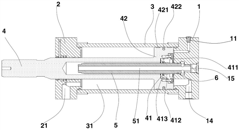
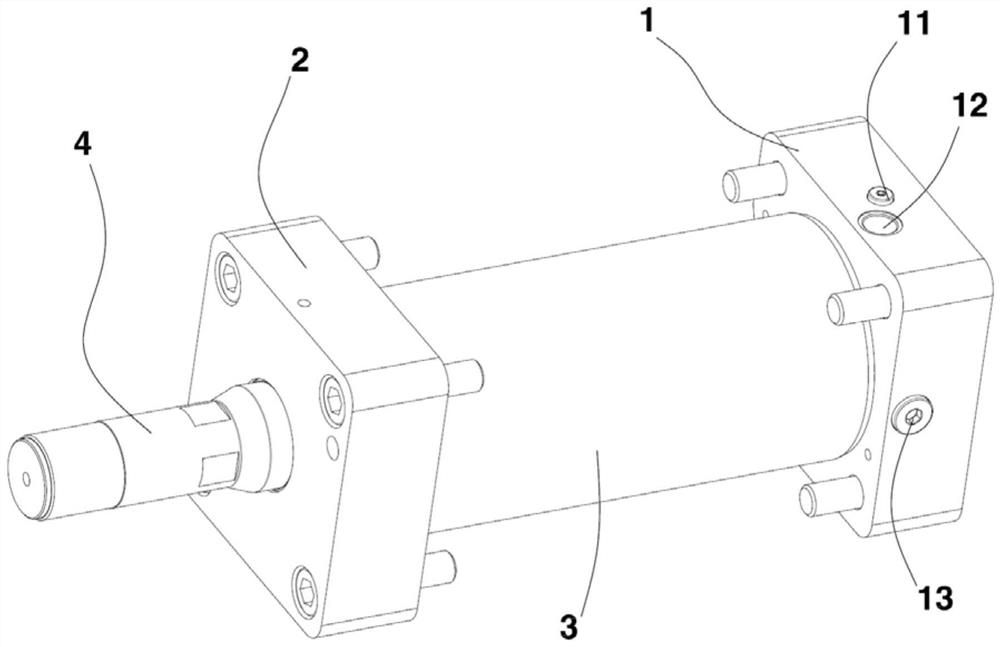
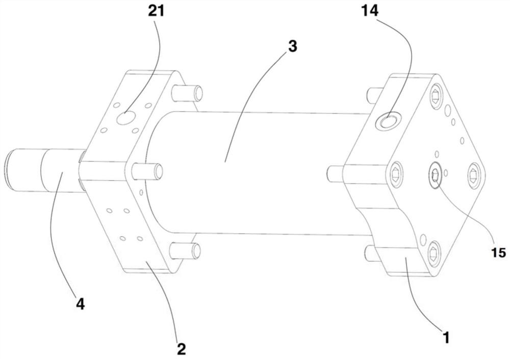
[0026] Such as Figure 1 to Figure 5 As shown, a double-cylinder rapid injection structure of an injection molding machine includes an oil cylinder 3, a front cover 2, a rear cover 1, a differential rod 5, and a piston rod 4; the front cover 2 and the rear cover 1 are located at both ends of the oil cylinder 3 , the differential rod 5 is a hollow structure, the tail of the differential rod 5 is arranged in the back cover 1, and the head extends to the front cover 2; the rear part of the piston rod 4 is provided with a cavity, and the piston The rod 4 is sleeved outside the differential rod 5, and the head of the piston rod 4 passes through the front cover 2 and is slidably connected with the front cover 2;

[0027] The tail of the piston rod 4 is provided with a shaft cover 41 slidingly fitted with the differential rod 5, the shaft cover 41 i...


PUM


Abstract

A double-cylinder quick injection structure of an injection molding machine comprises an oil cylinder barrel, a front cover, a rear cover, a differential rod and a piston rod; the front cover and the rear cover are located at the two ends of the oil cylinder barrel, the differential rod is through front and back, the tail of the differential rod is arranged in the rear cover, and the head of the differential rod extends towards the front cover; and a cavity is formed in the rear portion of the piston rod, the piston rod is arranged outside the differential rod in a sleeving mode, and the head of the piston rod penetrates through the front cover and is connected with the front cover in a sliding mode. Through holes are oppositely formed in the two sides of the tail of the differential rod, an annular cavity surrounding the through holes is formed in the rear cover, and a first oil port and a second oil port which supply oil to the differential cavity through the annular cavity and the through holes are formed in the rear cover, so that the flow can be reduced, and control is more accurate; and rapid injection molding of the large-diameter piston rod can be achieved, and injection molding processing has the advantages.

Description

technical field [0001] The invention relates to the technical field of injection molding machines, in particular to a double-cylinder rapid injection structure of an injection molding machine. Background technique [0002] The injection unit of the existing injection molding machine usually adopts a single-cylinder design, and the structure is relatively simple; when the plastic melts, the hydraulic motor drives the spline shaft to rotate, and the spline shaft drives the injection piston to rotate through the spline, and the injection piston drives the screw to rotate. Pushed by the plastic melt at the front end, the injection piston retreats along the spline on the spline shaft; when injecting, the oil port enters the pressure oil, which pushes the injection piston forward, and the injection piston pushes the screw forward to inject molten plastic into the mold; Existing injection molding machines have problems such as large piston rod diameter, slow injection speed, and in...

Claims


Application Information

Patent Timeline
Patent Type & Authority Applications(China)
IPC IPC(8): B29C45/53B29C45/58
CPCB29C45/53B29C45/58
Inventor 杜严庆潘彩芳徐晓东徐定俊
Owner 宁波甬华塑料机械制造有限公司
Why Eureka
Try Eureka