Jet reverse thrust runner structure

A runner and anti-thrust technology, applied in the direction of engine components, machines/engines, mechanical equipment, etc., can solve the problems of jet reverse thrust runner disintegration, damage to generator sets, circumferential asymmetry, etc., to avoid torque loss, Effect of reducing resistance torque and highlighting rigidity

Pending Publication Date: 2022-02-08
朱宁 +1
View PDF0 Cites 0 Cited by
  • Summary
  • Abstract
  • Description
  • Claims
  • Application Information

AI Technical Summary

Problems solved by technology

After careful understanding, I found that these so-called jet thrust reverse technologies are all behind closed doors. I only know the principle, but I don’t know that the jet thrust reverse structure is easily accompanied by radial asymmetry, circumferential asymmetry, radial shaft beating and centrifugal force. I don’t understand it at all. The operation of all jet reverse thrust principles must be based on the premise of overcoming radial asymmetry, circumferential asymmetry and centrifugal force. All asymmetry and centrifugal force will eventually directly lead to the disintegration of the jet thrust reverse runner, or rapid damage due to violent shaft beating For the entire generator set, it is obvious that these extremely destructive accompanying factors have not been effectively overcome, which is the key reason why these primary technologies are generally neglected by society

Method used


Image

  • Jet reverse thrust runner structure
  • Jet reverse thrust runner structure
  • Jet reverse thrust runner structure

Examples


Embodiment Construction

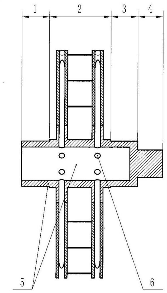
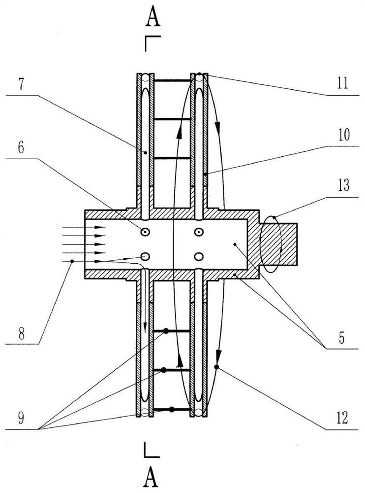
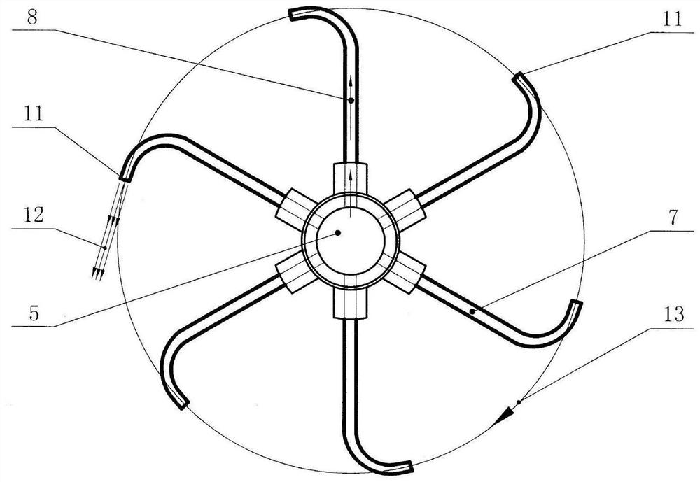
[0029] see Figure 1-Figure 5 , is an embodiment of a jet reverse thrust runner structure of the present invention.

[0030] exist figure 1 Among them, the supporting section 1 at the open end of the hollow shaft, the supporting section 3 at the tail end of the hollow shaft and the torque output connecting section 4 are mainly used to support, seal and connect the engine shaft; the middle of the two supporting sections is the torque generating section 2, which mainly functions It is fixedly connected with the tubular anti-thrust arm 7. Since the functional structures of these four functional segments have become universally known structures, they are only represented by segments in the accompanying drawings of the present invention.

[0031] exist figure 2 In the shown embodiment, the supporting section 1 at the open end of the hollow shaft, the torque generating section 2, the supporting section 3 at the tail end of the hollow shaft and the torque output connection sectio...


PUM


Abstract

The invention discloses a jet reverse thrust runner capable of efficiently utilizing jet reverse thrust acting force and a large force arm to generate torque. A hollow shaft open end support section, a torque generation section, a tail support section and a torque output section are sequentially arranged on a hollow shaft. A plurality of groups of tubular reverse thrust arms are uniformly arranged on the torque generation section of the hollow shaft, each group of tubular reverse thrust arms comprises 3-20 tubular reverse thrust arms, and the bottom ends of the tubular reverse thrust arms are communicated and fixedly connected with the hollow shaft. Flange-shaped permeable reinforcing ribs are respectively arranged on the left side and the right side of each group of tubular reverse thrust arms, and a plurality of axially spaced positioning reinforcing ribs are arranged between two adjacent flange-shaped permeable reinforcing ribs. When a driving medium with pressure potential energy enters the hollow shaft from the open end of the hollow shaft, the driving medium can only pass through a through hole and the tubular reverse thrust arms and is finally sprayed out at a high speed from reverse thrust spraying holes in the top end of the tubular reverse thrust arms. The turbine element and the negative influence of the prior art are thoroughly eliminated, and the reverse thrust acting force is intensively generated at the maximum force arm, so that the torque generating efficiency is extremely high.

Description

technical field [0001] The invention relates to the technical field of runner structures, in particular to a jet reverse thrust runner structure. Background technique [0002] At present, according to different driving media, traditional generators are mainly divided into: gas generators, steam generators, hydroelectric generators and wind generators. Although the structure of the runners that drive the generator rotor is quite different due to the difference in the driving medium, they all have the same essential features: First, the driving medium is used to impact the runner blades at high speed, so that the runner blades are axially Forced, through the turbine principle, the runners are rotated, and finally the generator rotor is driven to generate electricity. Therefore, according to different driving media, the complete names of each runner are: gas turbine, steam turbine, water turbine, wind turbine. According to the turbine principle, any mechanical structure that i...

Claims


Application Information

Patent Timeline
Patent Type & Authority Applications(China)
IPC IPC(8): F01D1/32F01D25/00
CPCF01D1/32F01D25/00
Inventor 朱宁陈蓓蓓
Owner 朱宁
Why Eureka
Try Eureka